Fieldbus Software Tools
Ethernet is now established as the preferred network for business and control layers in industry. In factory automation and the power industry it is established as the device level network of choice. In process automation it is becoming established for high bandwidth applications such as cameras and analysers and is forecast to be adopted at device level.
The deployment of Ethernet into process automation has been hindered by the gas or dust hazardous area classification in which the end device is often installed. The high installation costs of the mechanical protection methods required to install general purpose Ethernet in hazardous areas, together with the maintenance limitations, have reduced the uptake of both wired and wireless Ethernet. Many end users prefer to use intrinsic safety for low power hazardous area applications, such as instrumentation, having made significant investment in training their design, installation and maintenance staff in the technology.
IS Ethernet has been adopted for communications across hazardous areas using copper for short distances and fibre for long distances. It provides WLAN infrastructure for the mobile operator using Intrinsically Safe mobile computers and tablet PCs, reducing installed cost and simplifying architecture with IS serial devices and providing automation infrastructure in coal mines. High definition intrinsically safe Ethernet cameras have been widely adopted in mining and process applications, allowing operators to monitor critical systems from a safe environment
Our range of Instruments provide gas-analyser solutions across a wide range of industrial applications. If you are unable to find an appropriate product, please call us on +44 (0)1582 435600 or .(JavaScript must be enabled to view this email address).
Ammonia, NH3, is an anhydrous compound of nitrogen and hydrogen. By using an Ammonia Dissociator, the anhydrous ammonia can be separated or “cracked” into its constituent components of Nitrogen and Hydrogen, thus providing a cost effective way to generate hydrogen.
When ammonia dissociates it does so according to the following chemical equation: 2NH3 → N2 + 3H2
Hydrogen, ammonia and nitrogen will be present in precise proportions depending on the degree of dissociation and so it is important to measure the percentage dissociation of ammonia for process control and optimisation.
Hydrogen has a significantly different thermal conductivity to ammonia and nitrogen, which means that a measurement of the mixture’s thermal conductivity allows the amount of hydrogen and hence the amount of ammonia to be calculated.
The MTL katharometer based thermal conductivity analysers are ideal for making measurements of these mixtures and can be configured to provide output of % Hydrogen, % Ammonia or % Dissociation.
Please view the product information for our ammonia analyser range using the links below. If you are unable to find an appropriate product, or require assistance please contact our specialist team on +44 16 98 90 72 62 or .(JavaScript must be enabled to view this email address).
Gaseous nitrogen has a wide variety of industrial applications and more nitrogen is used industrially than any other gas. Nitrogen is commonly thought of as an inert gas and it is the non-reactive properties of nitrogen that make it so highly valued especially for gas blanketing applications. Nitrogen is also used in a broad range of industries, including chemi-pharma and oil and gas to metal refining and fabrication processes.
However, nitrogen is a difficult and expensive gas to measure. Therefore, an alternative solution is to measure the level of impurities, which is an accepted method for measurement of N2 purity. The MTL katharometer (thermal conductivity) range of analysers are ideal for measuring the amount of N2 present in binary or pseudo-binary gas mixtures, whilst our range of galvanic (G range) or zirconia (Z range) oxygen analysers are well suited to measure residual oxygen for nitrogen purity applications
Please view the product information for our nitrogen analyser range using the links below. If you are unable to find an appropriate product, or require assistance please contact our specialist team on +44 16 98 90 72 62 or .(JavaScript must be enabled to view this email address).
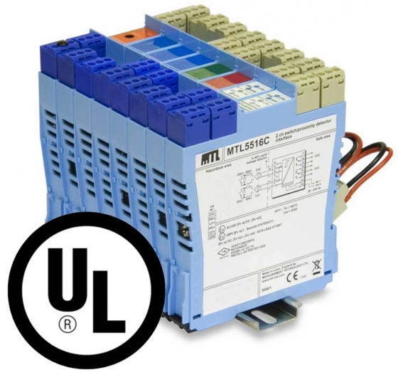
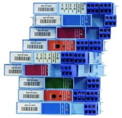
Our MTL5500 range of Intrinsically safe isolators, now have UL Approval, are UL labelled and are in stock. All available models numbers are listed below.
The MTL5500 range modules are versatile yet simple to apply; use the latest technology and yet are well proven.
These contrasting attributes stem from the progression of our expertise in the design and manufacture of isolators for intrinsic safety and the application of innovative technology to achieve the required separation and segregation of the circuits.
The MTL5500 (DIN-rail mounting) and MTL4500 (backplane mounting) isolators share a common design, differing only in the mechanical mounting and connection methods.
- Compact modular design with DIN rail mounting
- High packing density
- Single and multi-channel I/O modules
- 3-port isolation with low power dissipation
- Compatible with MTL5000
MTL5500 with UL approval - Stock availability |
|
| In stock |
Build to order
|
| MTL5510 |
MTL5510B |
| MTL5511 | |
| MTL5513 | |
| MTL5514 | |
| MTL5516C | |
| MTL5517 | |
| MTL5521 | |
| MTL5522 | |
| MTL5523 | MTL5523V |
| MTL5524 | MTL5523VL |
| MTL5525 | |
| MTL5526 | |
| MTL5531 | |
| MTL5532 |
|
| MTL5533 | |
| MTL5541 | |
| MTL5541S | |
| MTL5544 | |
| MTL5544D | |
| MTL5544S | |
| MTL5546 | |
| MTL5546Y | |
| MTL5549 | |
| MTL5549Y | |
| MTL5575 | MTL5576 |
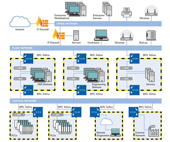
Supervisory Control and Data Acquisition (SCADA) and industrial control systems have long been considered immune to the cyber-attacks suffered by corporate information systems. The move to open standards such as Ethernet TCP/IP and web technologies has seen control systems affected by a growing number of both malicious and non-malicious network security events impacting critical infrastructure and manufacturing industries.You may never be attacked by a serious hacker, but typical control networks are extremely vulnerable to simple day to day security and reliability issues. Human errors, poor network segmentation and unprotected points of entry into the network, ‘soft’ targets such as un-patched PCs and vulnerable PLCs, can result in significant production losses and even safety issues.
Traditional firewalls are too complex for most security professionals to configure correctly and are even harder to set up properly on the plant floor. Control devices and protocols offer limited authentication, integrity or confidentiality mechanisms and can be completely controlled by any individual that can “ping” the device. Nor can they be easily patched or have security features added to them even when security vulnerabilities are discovered.
The MTL Tofino™ Industrial Security Solution is much more than just a firewall. It has revolutionised the approach of control system cybersecurity by introducing ‘Enforcer modules’ for popular Industrial Control System protocols in IEC 62443 ‘Zones’ and ‘Conduits’, providing a ‘defence in depth’ architecture. The system changed the way industrial ethernet security is managed by providing an intrinsically secure solution right out of the box. This provides a simple, effective cybersecurity solution for control and automation engineers which does not require IT skills for configuration and installation. The Tofino Configurator (TC) platform will configure, monitor and manage the functions of each remote Tofino™ Appliance so that it can be automatically tuned to meet the security needs of the devices it is protecting.
The 9202-ETS is our new second generation Tofino™ solution that continues to provide the highest level of network security with the great benefits of its predecessor with added features for further customer value. It is exceptionally easy to install compared with alternative systems and includes the latest configurator software to protect industrial networks from cyber-security vulnerabilities. This maximises plant uptime and process availability while protecting it from a network attack.
The MTL Tofino™ security solution is a package consisting of the 9202-ETS MTL Tofino security appliance hardware, 9211-TC Tofino Configurator (TC) and any additional Loadable Security Modules (LSMs) if required. Select the 9202-ETS icon below for more information.
This latest solution is backwards compatible with its predecessor the 9211-ET and the CMP software. As part of the second generation release a migration path has been developed to support our existing installed base. Please contact our technical support team for more information.
To download a copy of the MTL Tofino security solution brochure click here
To download the release note that describes the firmware upgrade available for version 1.8.0 of the MTL Tofino 9211-ET hardware click here.
For further information contact .(JavaScript must be enabled to view this email address).
More information is also available on our Eaton cybersecurity website.
Content for Application Notes
Our white papers are not only a means to demonstrate how our technology solutions can best address your needs; but an opportunity for us to share with you a wealth of industry knowledge and expertise. You can view or download your copy by simply clicking on the description text against the white paper of your choice.
We also offer a range of Application Notes that provide background information on specific MTL product ranges including some useful aspects and applications of a particular technology.
We hope you will find these both useful and informative.
Welcome to the brochures & posters index. Here you can access and download the latest literature for our MTL product line by simply selecting the relevant brochure or poster you are interested in. You can also filter by category via the drop-down menu. Printed copies are available on request - just email the .(JavaScript must be enabled to view this email address) with your requirements.
With process plants now spread over wide areas and the demand for more information, the transfer of electrical signals present many challenges. High power devices mixed in with low level signal transfer generates an environment which has an adverse effect on the ability to control and measure the processes.
Signal conditioning makes a major contribution to resolving issues such as varying grounding potentials, reducing signal noise and eliminating earth loops. It also protects sensitive control equipment from dangerous voltages. All these benefits add up to reduced down time, fewer failures, greater product yield and significant cost savings.
View the PDF Brochure for the MTL1000
By using signal TI multiplexing in process systems, the cost of installed wiring can be reduced by up to 50%. Further savings are achieved by reducing the number of inputs to the host, cabinet space and weight.
In Functional Safety, applying the generic standard IEC 61508 or the process industry sector standard IEC 61511…
The Safety Integrity Level (SIL) is essentially a measure of the probability for the availability of a Safety Instrumented Function (SIF) to take a process to a safe state upon demand.
The SIL applies to the whole SIF rather than to an individual element.
To achieve the required availability of a SIF then multiple parallel or redundant instrument loops are often needed, with voting in the ‘logic solver’ to resolve the status. Thus the SIF, or parts of the SIF, may be structured as 1oo1 (One out of One), 1oo2, 2oo3, etc to achieve the requisite low probability of failure.
This also follows from the need to follow IEC 61511 requirements for hardware fault tolerance, such as…
Our range of IS displays come in both panel and field mounting options. In addition to the user configurable loop powered indicators, are ‘mini HMI’ text and graphics that displays that provide operator input and control via a host computer.
To find out more about MTL training, available course dates, costs or to arrange an on-site course please contact:
Tel: +44 (0)1582 407535 Email: .(JavaScript must be enabled to view this email address)
Alternatively please contact your local account manager
Through these live webinars learn more about how MTL products can help you solve your hazardous area connectivity problems. Each webinar ends with a Q&A session.
This cross reference is intended to be used as a tool to determine an equivalent MTL Isolator or Barrier part number based on another manufacturer’s part number. Once you submit the information MTL technical Support team will inform you with the appropriate MTL equivalent part number.
MTL has built an outstanding reputation over the last 40 years for supplying quality products into some of the harshest environments known. We are proud to stand as a world leader in Intrinsic Safety, and continue to lead the way in the development of FOUNDATION™ Fieldbus components for harsh and hazardous areas. MTL’s training courses have been an industry staple for many years, and continue to provide best in class education for technical managers, engineers and technicians involved in the design and selection of apparatus in the process industries.
Why Choose MTL Training?
- You will be trained by experienced industry professionals
- The training is grounded in the practical application of Intrinsic Safety and FOUNDATION™ fieldbus technology
- First-class supporting materials are provided for each learner
- MTL has an establish track record in offering education courses
- Each course uses a variety of media, to provide a stimulating learning environment
Course Portfolio
- Foundation Fieldbus principles and physical layer design - 1 Day (UK only)
The growth in open architecture in the process automation industry is founded on standard fieldbuses, providing fast, reliable digital communication between field devices and control systems. This course will describe the fundamental principles of FOUNDATION™ fieldbus networks, and how they are implemented in control systems for safe and hazardous area applications. There will be an emphasis on the design of the fieldbus ‘physical layer’, meaning the electrical field network comprising power supplies, wiring and field device couplers. This course will be of particular relevance to anyone involved in the selection, specification, installation, commissioning and maintenance of fieldbus networks, particularly in a hazardous environment.
Subjects covered include:
Comparison between 4-20mA and fieldbus instrumentation systems
Benefits and drawbacks of fieldbus networks
Introduction to the fieldbus ‘physical layer’
Foundation Fieldbus definitions
Boundary conditions for designing reliable networks
Permitted cable types
Consideration of failure modes
Designing networks for high availability
Fieldbus power supply types, redundancy and failure signaling
Field device couplers
Taking fieldbus networks into hazardous areas
Fieldbus Intrinsically Safe Concept (FISCO)
Fieldbus Barriers
Physical layer diagnostics
- Introduction to ATEX, DSEAR and Intrinsic Safety - 1 Day (UK only)
Where process industries involve explosive atmospheres, the ATEX Directives - 94/9/EC (100a) and 1999/92/EC (137) lay down European legal requirements. In the UK, the implementation of these directives is found in the Dangerous Substances and Explosive Atmospheres Regulation (DSEAR), which details the user’s responsibilities. The application of the directives to installation practice are described, with reference to relevant Codes of Practice. The course also introduces the main international systems for the classification of flammable atmospheres, and describes the principles and implementation of the Intrinsic Safety protection method for electrical apparatus. The seminar is targeted at electrical and instrument engineers, technicians and other qualified engineers involved in the safe use of intrinsic safety equipment and its use in potentially explosive atmospheres.
Subjects covered include:
Explosions - causes and consequences
Review of current practice in Gas, Temperature and Area Classification
Behaviour of flammable gases and vapours
The ‘fire triangle’, flammable range, vapour density and flash point
Combustible dusts and powders
IEC standards applied to electrical equipment
Understanding ATEX terminology
Dangerous Substances and Explosive Atmospheres Regulations (DSEAR)
ATEX Equipment protection Levels (EPLs)
Equipment marking requirements
The Ex methods of protection: Ex d, Ex e, Ex p, Ex n, Ex m, Ex o, Ex i, Ex q
Origins and principles of Intrinsic safety
Shunt zener diode barriers and galvanically isolating interfaces
Simple Apparatus
Applications of Zener barrier and isolators – worked examples
Installation, earthing, maintenance and inspection requirements
Safety parameter matching and cable parameter calculation
The courses are conducted by arrangement at premises of your choice, and to suit the individual needs of your workforce. Courses are charged per day, plus the trainer’s travel and subsistence costs where applicable. There is no fixed limit on the number of learners, but a maximum of 20 is recommended to encourage participation. Multiple-choice questions will be used where appropriate to check participant understanding of key subject matter.
To find out more about MTL training, costs or to arrange an on-site course please contact:
Philip Saward, Training & Technical Consultant, Tel: +44 (0)1582 407272 or email: .(JavaScript must be enabled to view this email address)
Contains the answers to the questions we’re most often asked. Use the selection below to narrow you search.
Learn more about our company as well as product, applications and demos.
As products become obsolete, we offer as many options for a replacement product as possible. This information can be found by searching for the obsolete product by part number listing below:
Disclaimer:
Every effort has been made to ensure the accuracy of this information. MTL Technical Group recommends verification of the information necessary to make the appropriate product selection and the safety calculation for a given application.
Information in this cross reference is subject to change without prior notice.
Product Support Notes (PSN) and Tech Support Notes (TSN) are provided by MTL Technical Support Group as helpful references for our customers.
These products are stringently tested and certified following the latest guidelines and regulations dictated by the certification agencies.
After 30 years of successful development, the MTL Gas Analysis range is firmly established as your first choice for process gas analysers. Our products are used across a variety of applications in all environments, including hazardous areas, and across all industrial and process sectors.
We supply a broad range of products from OEM Sensors through to turnkey gas analysis systems.
For a brief overview of the range of products available click here
You can find your local Gas Analyser distributors in the contact us section.
If you require assistance please contact our specialist team on +44 16 98 90 72 62 or .(JavaScript must be enabled to view this email address).
MTLgas is partnering with specialist company BW Technology to enhance our customer service experience for pre-sales, order and after-sales support for MTLgas products.
The MTL Gas range of OEM gas sensor solutions are based on our non-depleting katharometer (K range) and zirconia (Z range) sensor technology. Our sensors are manufactured to the highest specification for integration into a wide range of systems where fast, accurate and reliable measurements are required.
Please view the product information for our gas sensor range using the links below. If you are unable to find an appropriate product, or require assistance please contact our specialist team on +44 16 98 90 72 62 or .(JavaScript must be enabled to view this email address).
Our Carbon Dioxide and Carbon Monoxide gas analyser range uses either our katharometer thermal conductivity sensor or infrared sensor with the most suitable sensor technology being determined by the application. Each of these sensor technologies is extremely stable and maintenance free, as well as being highly reliable and accurate.
Please view the product information for our carbon dioxide analyser range using the links below. If you are unable to find an appropriate product, please contact our specialist team on +44 16 98 90 72 62 or .(JavaScript must be enabled to view this email address).
The Noble gases; Helium (He), Neon (Ne), Argon (Ar), Krypton (Kr), Xenon (Xe) and Radon (Rn); are colourless, odourless and tasteless, nonflammable gases that make up 0.9% of the air. The noble gases are inert; a property which makes them very useful in a wide range of industries. Our non-depleting katharometer (K range) product range are ideally suited to measurement of these gases with our sensors being designed and manufactured to the highest standards, offering enhanced reliability and accuracy.
Please view the product information for our noble gases range using the links below. If you are unable to find an appropriate product, or require assistance please contact our specialist team on +44 16 98 90 72 62 or .(JavaScript must be enabled to view this email address).
The requirement to accurately monitor hydrogen when electrolysing brine (NaCl) to produce chlorine and sodium hydroxide is crucial process safety and efficieny. Not only does the KK650 monitor hydrogen but also chlorine purity. The KK650 hydrogen in chlorine analyser is based onour own in-house thermal conductivity expertise.
Please view the product information for our chlorine analyser range using the links below. If you are unable to find an appropriate product, or require assistance please contact our specialist team on +44 16 98 90 72 62 or .(JavaScript must be enabled to view this email address).
Landfill gas and biogas is produced by the biodegradation of waste. Landfill gas is a natural by-product of the decomposition buried general waste as found at rubbish dump sites whilst biogas is produced by controlled degradation of plant and animal waste products, i.e. contained in a sealed digester tank. Both gases are a complex mix of different gases, comprising mainly of methane (CH4) with the remainder being mostly carbon dioxide (CO2). The methane component is either recovered as fuel or flared off as waste.
Our landfill gas /biogas analysers are designed to provide reliable and accurate measurement of gases, helping to optimise plant productivity and improve plant availability.
Please view the product information for our biogas analyser range using the links below. If you are unable to find an appropriate product, or require assistance please contact our specialist team on +44 16 98 90 72 62 or .(JavaScript must be enabled to view this email address).
View our on-line Biogas overview brochure
Hydrogen is the most abundant chemical element in the universe and many industries and applications require hydrogen gas measurement to meet safety, regulatory, and process control requirements.
Since hydrogen has the highest thermal-conductivity value of all gases, our range of katharometer (thermal conductivity) analysers are ideal for measuring the amount of H2 that is present in a gas.
Please view the product information for our hydrogen analyser range using the links below. If you are unable to find an appropriate product, or require assistance please contact our specialist team on +44 16 98 90 72 62 or .(JavaScript must be enabled to view this email address).
Our Oxygen analyser range utilise either long life galvanic (G range) or non-depleting zirconia (Z range) sensor technology. Your individual application requirements will determine the best technology to use and the most suitable analyser model. Our sensors are designed and manufactured to the highest standards offering enhanced reliability and accuracy. Our oxygen analyser instruments are available in a range of configurations to suit all requirements from robust transportables to fixed installations.
Please view the product information for our oxygen analyser range using the links below. If you are unable to find an appropriate product, or require assistance please contact our Gas Analyser team on +44 16 98 90 72 62 or .(JavaScript must be enabled to view this email address).
MTL products are often specifed for projects because of particular
- Shell Nanhai/CNOOC, China - selects MTL power conditioners and Megablock wiring hubs.
- Shin-Etsu, Netherlands - refits 35 Foundation™ fieldbus segments using F650 power conditioners.
- Carbowil Spolka z.o.o. - uses MTL9112NI FNICO power supplies and Megablock wiring hubs to cocer key CO2 production process.
- Shanghai SECCO - install MTL fieldbus power conditioners to drive 2473 segments using Megablock wiring hubs.
- Ineos Chlor, UK - use MTL FPS-I power conditionersand Megablock wiring hubs in major chlor-alkali plant re-fit.
We operate across many diverse markets - from renewable energy sources to traditional Oil and Gas: from Pharmaceutical manufacturing to wastewater treatment and the group is recognised as a world leader in the development and supply of intrinsic safety explosion protection devices; fieldbus and industrial networks; lightning and surge protection and gas analysis equipment.
Many of the world’s safety-critical processes are monitored, controlled or protected by our MTL products. We are distinguished by our global network of sales and support centres and by its acknowledged position as thought leader in this high technology marketplace.
MTL regard technical support as a major part of their business and endeavour to provide assistance on enquiries both pre and post sales. Listed below are the source headings of information that is available directly via this section along with a brief description. If the information you require is not available on this web site, we advise users to contact their local office in order to obtain assistance directly.
 The SIL725 Safety Annunciator is designed and manufactured to provide a high safety integrity for critical alarm applications and for use as a component part of a safety instrumented system. The unit is third party certified by SIRA using the CASS methodology to a safety integrity level of SIL2.
The safety manual for the item can be found here: im.SIL725.pdf
sil725.sira.pdf
When MTL designs a product in the expectation that it will be used in functional safety-related systems, both the design process and the product needs to comply with IEC 61508:2010.
MTL has chosen to obtain Functional Safety Management (FSM) certification for the company. FSM means that MTL has the necessary processes and competence to design products according to IEC 61508:2010. Certification means that a notified body is ensuring that our processes are correct and that we are working to them. Together, FSM Certification gives our customers confidence in the company and the use of our products for functional safety.
The MTL4840 and MTL4850 HART multiplexers do not provide a safety function but are frequently applied alongside safety shutdown systems with connection to the analogue loops. In practical terms the concern for the multiplexer is that by making a connection to the safety loops there must not be an adverse effect on the analogue values that are being monitored and controlled by the safety system.
For the MTL4840 the non-interference by the multiplexer is affirmed in the certificate issued by Baseefa: BAS01SP9449X.pdf
Similar documents for the MTL4850 multiplexer are in preparation and will be listed here soon.
 To design, implement and prove the operation of functional safety loops, the engineer should refer to the information contained in the individual Safety Manuals for all of the elements that are providing a safety function. To design, implement and prove the operation of functional safety loops, the engineer should refer to the information contained in the individual Safety Manuals for all of the elements that are providing a safety function.In some instances just the hardware failure rates of the components may be required for comparison and calculation; this information is contained in the Data Declaration. For MTL4500/5500 series isolators we provide the following Data Declarations: |
||
| MTL4500 Series | ||
| MTL4501-SR | MTL08FMEA4501_1 | |
| MTL4504 | MTL10FMEA4504_1 | |
| MTL4511,MTL4514,MTL4516,MTL4516C,MTL4517 | MTL08FMEA4517_3 | |
| MTL4521 | MTL08FMEA4521_2 | |
| MTL4521L | MTL10FMEA4521L_1 | |
| MTL4523,MTL4523R,MTL4524,MTL4524S,MTL4525 | MTL08FMEA4523_3 | |
| MTL4523L | MTL08FMEA4523L_2 | |
| MTL4523V | MTL10FMEA4523V_1 | |
| MTL4526 | MTL10FMEA4526_1 | |
| MTL4541 | MTL08FMEA4541_2 | |
| MTL4541S | MTL10FMEA4541S_1 | |
| MTL4544 | MTL08FMEA4544_1 | |
| MTL4544D | MTL09FMEA4544D_1 | |
| MTL4546 | MTL08FMEA4546_1 | |
| MTL4546C | MTL08FMEA4546C_1 | |
| MTL4546Y | MTL09FMEA4546Y_1 | |
| MTL4549,MTL4549C,MTL4549Y | MTL08FMEA4549_1 | |
| MTL4561 | MTL09FMEA4561_2 | |
| MTL5500 Series | ||
| MTL5501-SR | MTL08FMEA4501_1 | |
| MTL5511,MTL5514,MTL5516C,MTL5517 | MTL08FMEA4517_3 | |
| MTL5521 | MTL08FMEA4521_2 | |
| MTL5522 | MTL08FMEA5522_2 | |
| MTL5523,MTL5524 | MTL08FMEA4523_3 | |
| MTL5523V | MTL10FMEA4523V_1 | |
| MTL5525 | MTL08FMEA5525_2 | |
| MTL5526 | MTL10FMEA4526_1 | |
| MTL5541 | MTL08FMEA4541_2 | |
| MTL5541S | MTL10FMEA4541S_1 | |
| MTL5544 | MTL08FMEA4544_1 | |
| MTL5544D | MTL09FMEA4544D_1 | |
| MTL5546 | MTL08FMEA4546_1 | |
| MTL5546Y | MTL09FMEA4546Y_1 | |
| MTL5549,MTL5549C,MTL5549Y | MTL08FMEA4549_1 | |
| MTL5561 | MTL09FMEA4561_2 | |
Zener Barriers are normally considered as wiring connection equipment in the safety loops – they are passive coupling devices which in this context do not provide a safety function other than their hazardous area intrinsic safety protection. Below are links to documents  which will be of assistance to an engineer looking to compile the safety case analysis:
AN9036.pdf ~ Application Note that provides an introduction to Functional Safety and IEC 61508.
Fsafebar.pdf ~ Discussion of use of zener barriers in safety loops.
Tuv_bar ~ TuV position letter.
MTL isolating interfaces are alternatives to shunt-diode safety barriers for protecting electrical circuits in hazardous areas.
They need no high-integrity earth and provide extra features such as signal amplification and relay functions. The isolation of hazardous- and safe-area circuits allows each to be earthed at any convenient point, simplifying installation and avoiding earthloop problems.
MTL offers the best choice in DIN-rail and backplane mounting isolators to meet the requirements of modern control interfacing systems. The DIN-rail mounting isolator ranges provide a wide choice of functions with high accuracy and reliability, while the backplane mounting products are established as the leading IS system interface with solutions for all the major DCS companies.
The MTL4500 range is the latest generation of backplane mounting products, building upon the heritage of MTL4000 and introducing many key application benefits. The MTL5500 range launches a new industry standard for DIN rail mounting products, ideally suited to a wide variety of interface tasks for process instrumentation, complemented by the well proven MTL5000 range.
In most applications MTL4500 modules can directly replace MTL4000 models but check with MTL if you have any concerns. Similarly, MTL5500 supplants MTL5000 range as the DIN rail interface family of choice. With this mounting arrangement, it is practical for models from both families to be used alongside each other during the transition phase from the old range to the new.
The following table shows the wide range of approvals and certificates that apply to the MTL4500 and MTL5500 ranges:-
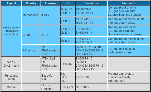
Note: there are many other local country or industry approvals for the products such as from Australia, Brazil, India, China, Russia, Japan, Korea, for example. For product certificates click here.
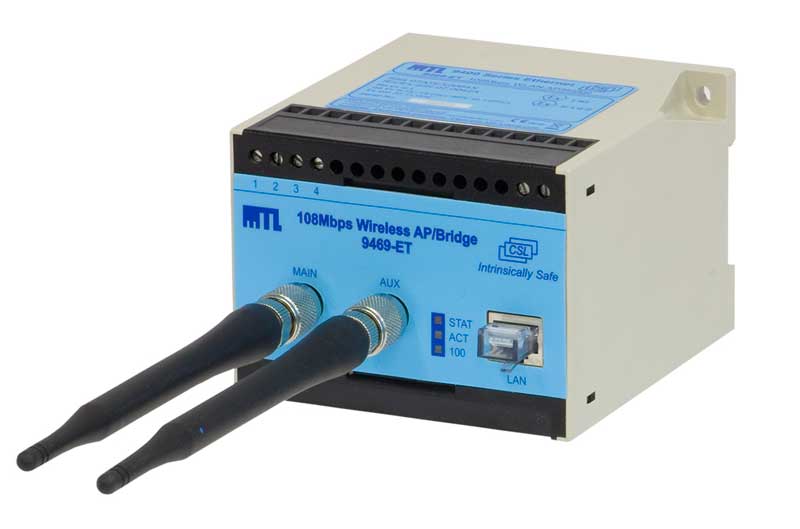
Our business dispels the myth about having equipment located in a hazardous area resulting in limitations on performance or technology selection. We combine the functionality and interoperability of proven technology with intrinsically safe design at its core. Our wireless hazardous area solutions are 802.11 compliant and have well supported Ethernet interfaces which can simultaneously provide power and data communications though a unique intrinsically safe power over Ethernet connection (PoEx). PoEx technology provides ease of connection while in hazardous area, is live workable and easy to maintain which reduces operational costs and promotes safer operation. When compared with equivalent Ex d solutions, our solution offers a physically smaller, lighter and lower cost of ownership product.
Our products feature selectable frequency ranges (2.4GHz and 5GHz bands), WDS (wireless distribution system) and 108Mbps data rates which ensure that your network can be deployed to avoid interference and give maximum signal coverage where required. Systems can be setup to simply provide a point to point Ethernet link or to give an operator access to the network while in the field as per conventional 802.11 networks.
Our hazardous area products possess the following capabilities:
- Mounting in Zone 1 Div 1 / Zone 2 Div 2
- 802.11 a/b/g wireless connectivity for maximum device support
- Intrinsically safe power over Ethernet (PoEx) or two-wire options
- WDS (wireless distribution system) access point to access point communication for maximum coverage
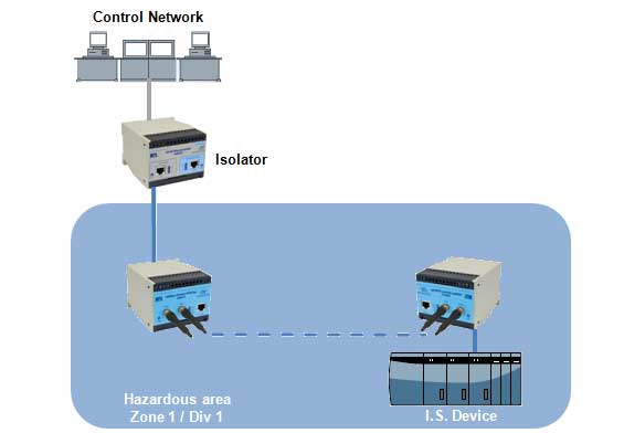
Point-to-point wireless Ethernet links in hazardous areas
Wireless network connectivity in hazardous areas
Related Products:
Our intrinsically safe (I.S.) wireless solutions provide completely safe wireless operation in hazardous areas.
Zone 2, Class 1 / Div 2 Hazardous Area 802.11
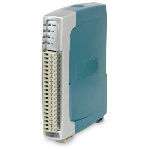
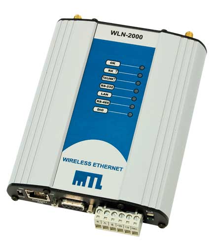
Cable marshalling and milliamp loop connections present significant cost and time during installation. These costs can be reduced through our Serial I/O to multiplexer by taking 16 digital or 8 digital with 8 analogue connections into a single device and transmitting the data over MODBUS. When interfaced with one of our wireless network, complete wireless I/O multiplexing systems can be deployed which maximise the opportunities of connections while significantly reducing cabling infrastructure. The I/O data can be transferred to outputs, re-creating the signal in a different location or made available to a SCADA / DCS or PLC though MODBUS protocol.
Our Process signal multiplexing delivers the following features:
- Three I/O versions with configurable input and output types
- MODBUS or Exception reporting protocol selectable
- RS232 and RS485 ports for standard connection to MODBUS master or into MTL wireless networks
- 0-20mA, 0-10V, pulsed and digital I/O available
- Router operation for connection between two Ethernet networks
- Selectable transmit power to suit application
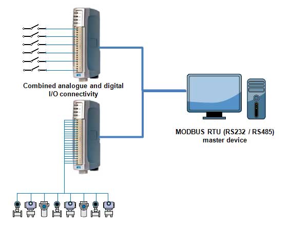
I/O to MODBUS RTU interface
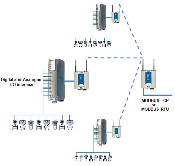
I/O interface to MODBUS TCP over wireless
Related Products:
MTL’s wireless serial I/O interfaces provide an easy way to connect sensors, transducers and switches.
Zone 2, Class 1 / Div 2 Hazardous Area 802.11
Our Ethernet modems provide wireless solutions in Zone 2, Class 1/Div 2 hazardous areas.
Cable marshalling and milliamp loop connections present significant cost and time during installation. These costs can be reduced through our Serial I/O to multiplexer by taking 16 digital or 8 digital with 8 analogue connections into a single device and transmitting the data over MODBUS. When interfaced with one of our wireless networks, complete wireless I/O multiplexing systems can be deployed which maximise the opportunities of connections while significantly reducing cabling infrastructure. The I/O data can be transferred to outputs, re-creating the signal in a different location or made available to a SCADA / DCS or PLC though MODBUS protocol.
The process signal cable replacement solution features:
- Out of the box solution – no configuration necessary for fast simple installation
- Receiver LED display of Received Signal Strength indication for easy site test and commissioning.
- 0-20mA, Digital and thermocouple inputs.
- Configurable set point output on receiver unit provides alarming for high / low levels on analogue
- License-free operation in 900MHz and 800MHz bands
- Small footprint radio
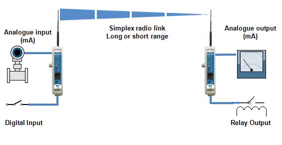
Point-to-point wireless I/O
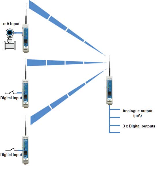
Multipoint-to-point wireless I/O
Related Products:
Wireless I/O
Connecting sensors and transducers into a display panel or HMI/SCADA interface can be a costly
Ethernet is seeing major growth in the process market for both network and field connections for bringing data back to the control room. Our business provides complete support for this growing technology, maximising the potential for easy network access and process data transfer. Our wireless Ethernet solutions can cover both hazardous (Zone1, Div 1, Zone 2, Div 2) and safe areas, providing secure networking for remote devices and/or mobile operators. Wireless connections can be made available over 802.11, GPRS / GSM and lower frequencies for increased range giving a complete portfolio suitable for full network infrastructure or device to network connections. We can also add value by introducing PPP serial connections over 802.11 networks further increasing the types of devices that can be connected through an 802.11 infrastructure.
Our wireless Ethernet solutions feature:
- 802.11 a/b/g connectivity for interoperability with existing networks
- STP (spanning tree protocol) for redundant wireless links
- WDS (wireless distribution system) for access point to access point communication, improving network deployment options
- Secure WPA (AES) encryption
- Router operation for connection between two Ethernet networks
- Selectable transmit power to suit application
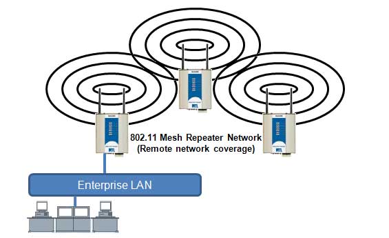
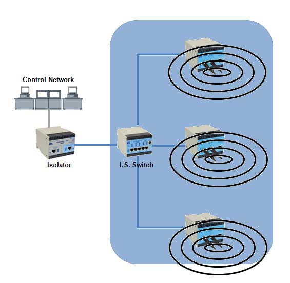
Multiple access points, one Ethernet connection
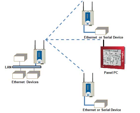
Access point with multiple clients
Related Products:
The MODBUS protocol is well supported as a standard for transferring instrumentation data back to a SCADA system or control PLC. Our wireless solution provides maximum flexibility within a single wireless device, possessing the capability to be deployed as a MODBUS TCP master, slave or transparently route data between devices. This in conjunction with the TCP to RTU conversion feature enables both serial and Ethernet MODBUS devices to be integrated seamlessly into a common wireless backbone. Remote configuration, secure encrypted communications and redundancy on a wireless link level ensure that a reliable, secure network is formed to transport the data. See Application Note AN9033 for additional information.
We also provide I/O interfaces as an additional connection method, supporting 4-20mA, digital and pulsed signal transfers for direct connection to instrumentation.
- MODBUS TCP Master or Slave operation
- TCP to RTU conversion integrates serial devices into Ethernet infrastructure
- Simultaneous Ethernet, RS232 and RS485 device connectivity
- Internal registers for data storage / transfer
- 802.11 a/b/g wireless networking for global license-free operation
- Individual poll timeout registers to indicate communications status
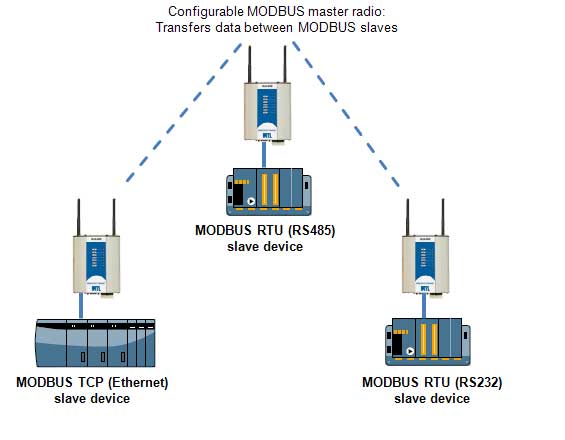
Stand alone wireless MODBUS transfer system between two slave devices
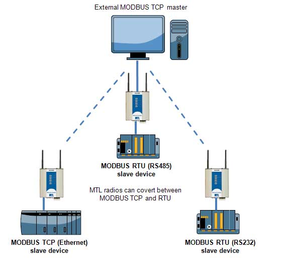
MODBUS SCADA integration example
Related Products:
Serial connectivity is a well established technology for devices on the market today, however providing cable runs for multiple devices can be costly particularly over long distances and can often be a limitation to device selection. We offer wireless serial networking solutions which boost the range and connection possibilities of serial devices such as PLCs, intelligent transducers and data loggers. Operating over a range of frequencies in addition to GSM/GPRS and 802.11 communication protocols, our wireless serial networks can be deployed for transparent operation in which all devices in the network forward on any serial data to their connected devices. Alternatively, systems can be setup in a controlled mode, ensuring that only the device that the data was intended for reaches the proper destination though addressing. Repeater functionality and encryption further extends the range, allowing secure network deployment possible in a wide array of situations.
Our wireless serial networking products provide:
• Simultaneous RS232 & RS485 connectivity over wireless
• Repeater functionality for long range networking
• Wide frequency ranges
• Hot redundant standby radio for fault tolerant wireless communication (400MHz products)
• Digital output for communications failure indication
• Remote configuration for easy network access
• Secure encryption to protect data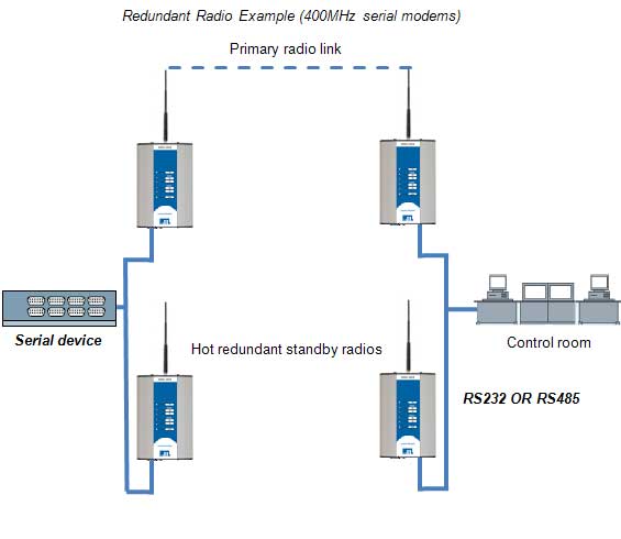
Redundant radio (400MHz system)
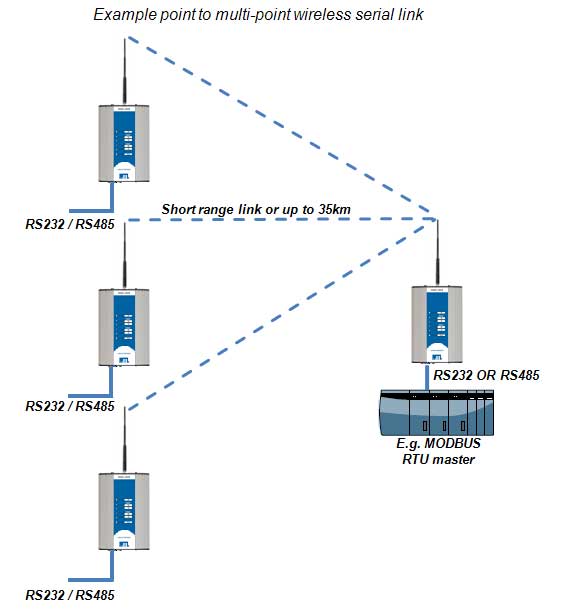
Point-to-multipoint wireless serial data transfer
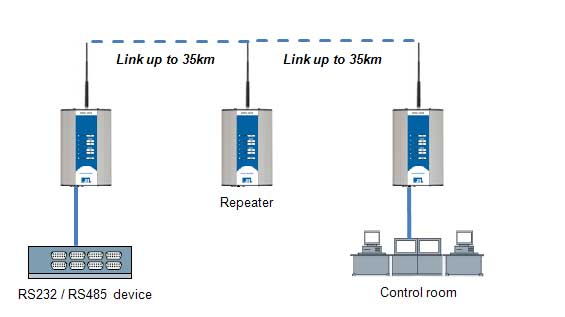
Wireless serial point-to-point link via repeater
Related Products:
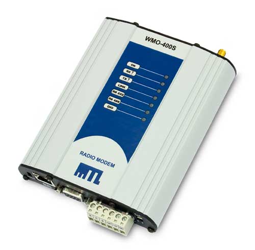
Wireless Serial Modems
Serial interfacing is one of the most well supported data transfer methods between industrial devices.
In today’s process industries there are increasing demands for greater efficiency, higher reliability and lower cost of ownership of field equipment and supporting networks. We offer full end to end or part solutions to meet the requirements of your project.
From plant-wide 802.11 network infrastructure in hazardous areas to simple sensor signal cable replacement, we bring the experience and the products to realise robust and secure wireless systems. Our wireless technology supports industry standard connections and protocols which maximizes the flexibility of your system while reducing inventory and installation costs.
To help you make your product choice, we have included below a product selector in which you can choose to view product by their application.
MTL offers a range of Application Notes that provide background information on specific MTL product ranges, types of products or some useful aspects or applications of a particular technology. These notes are provided free of charge for download.
 |
AN9030 - Availability, Reliability, SILA brief look at some of the terms that are frequently used in the world of SIL (Safety Integrity Level) and IEC 61508. Some helpful definitions of the terms and how to calculate them. Important basic information for those newly venturing into this potentially confusing area. Keywords: SIL, MTBF, MTTR, PFD, availability, reliability.
|
 |
AN9029 - Wireless Plant: Complete CoverageWireless communications are becoming an important part of a company’s infrastructure both outside and inside a plant environment. The wireless infrastructure can be used for both network and process data communication, however coexistence must be considered early in the design of plant-wide wireless systems. MTL are unique in being able to provide a mesh network infrastructure complete with I/O, gateways and IS equipment capabilities. Keywords: Wireless, Intrinsically Safe, Ethernet, PoEx.
|
 |
AN9028 - Asset Tracking in Hazardous AreasAsset Tracking of equipment and personnel is becoming an important component of a facility’s HSE compliance. The MTL range of Intrinsically Safe (I.S.) Ethernet products make it possible to have a suitable wireless infrastructure to access the associated chip readers anywhere in a facility, regardless of area classification. Keywords: Wireless, Intrinsically Safe, Ethernet, PoEx.
|
 |
AN9027 - FNICO Non-Incendive Fieldbus SystemA practical guide to the selection, installation and maintenance of equipment complying with the Fieldbus Non-Incendive COncept (FNICO) for fieldbus systems in Zone 2 and Division 2 hazardous areas. Keywords: FNICO, fieldbus, hazardous areas, FOUNDATION Fieldbus, H1
|
 |
AN9026 - FISCO Intrinsically Safe Fieldbus SystemA practical guide to the selection, installation and maintenance of equipment complying with the Fieldbus Non-Incendive COncept (FNICO) for fieldbus systems in Zone 2 and Division 2 hazardous areas. The document begins with a discussion of the origins of FNICO and follows with a review of the main elements to be considered when assembling FNICO systems. Further sections develop each subject in more detail. The intention is to provide clear guidance to new and experienced fieldbus users. Keywords: FISCO, fieldbus, intrinsically safe, hazardous areas, FOUNDATION Fieldbus, H1
|
 |
AN9025 - An Introduction to Functional Safety and IEC 61508This application note is intended to provide a brief introduction to the IEC 61508 standard, and to illustrate how it is applied. It does not claim to be a complete interpretation of the standard; that would be impossible in so few pages. However, it should be helpful, especially if the subject is new to you. Keywords: Functional safety, SIL, IEC61508
|
Designed with digital architectures in mind, the DeltaV™ system is a fully scalable I/O platform that integrates “smart plant” capabilities including HART®, FOUNDATION fieldbus™, high-speed discrete busses, and embedded advanced control. This seamless, intelligent field integration provides the infrastructure for advanced applications such as Asset Management Solutions (AMS) for quick, easy device re-ranging, configuration and diagnostics.
The product groups listed below have been tested by Emerson Process Management and found to be suitable for use in conjunction with DeltaV™ and PlantWeb®

MTL Instruments operates a continuous Product Development Policy and is constantly striving to meet customers needs and expectations. We are currently conducting some market research on the following subjects:
- Current and future trends of I/O products within the Process Control industry.
“Remote IO has become a proven method for interfacing field mounted sensors, transmitters, transducers and alarms directly to DCS and PLC based systems. The reduction in point to point wiring and the ability to send control signals over long distances has made distributed and remote I/O a preferred method for field device connectivity.” - Current and future potential of Wireless HART™ (WiHART) within the Process Control industry.
“Wireless HART (WiHART) is the latest technological addition to the family of HART enabled devices. Based on the HART 7 standard, the technology addresses issues within wireless sensor networks such as radio path uncertainty, reliability and power consumption.”
All information provided for either survey will be kept strictly confidential. Our sole purpose by conducting this survey is to sample the relevant market requirements from our customers viewpoint. By supplying your opinion to us in this format we can readily act on it to bring you an improved product or service in the ways that matter to you the most.
In return for your time and consideration, if you complete either survey by 30th November 2009 you will be entered into our prize draw to win a 32GB Apple iPod Touch. One qualifying entry will be drawn from each of the surveys and the winners notified as soon as possible.
|
LARGEST INSTALLED BASE - WORLDWIDE
Adopting the newest technology doesn’t mean that risks have to be taken when selecting hardware. MTL has been supplying the fieldbus market for over 10 years, and have the industry’s largest installed base of physical layer components. Third-generation power supplies and wiring components, and a decade of fieldbus experience, mean users can specify with confidence.
- Over 5,000 fieldbus installations
- 250,000 Megablock fieldbus device connections
- Used on the world’s largest fieldbus installations
FIELDBUS LEADERSHIP
MTL firsts…
- First ever fieldbus power conditioner
- First true redundant conditioning power supply
- First short-circuit protected wiring block: SpurGuardTM
- First IEC TS 60079-27 compliant FISCO power supplies
- First FNICO power supplies - still the definitive solution
- First FF-831 registered power supplies
- First multi-channel, redundant fieldbus power supply module
- First Fieldbus FoundationTM registered diagnostic module
APPLICATIONS SUPPORT
MTL has individually earned a reputation for the highest levels of pre- and postsales support. Trained local and regional sales and applications engineers are available to provide technical advice at every stage of the design cycle, to ensure trouble-free start up and rapid diagnosis of in-service problems. Engineering-led management is at the heart of MTL’s strategy for fieldbus success.
DIAGNOSTIC EXPERIENCE
MTL has extensive experience of diagnosing faults on fieldbus networks, and has established a technical lead in the manufacture and use of hand-held test equipment. Building on this experience MTL have released the first Fieldbus FoundationTM registered diagnostic module. This easily integrates diagnostics information into your choice of fieldbus control system with integrated help screens to assist with the rapid tracing and rectification of field faults.
CONTINUOUS PRODUCT DEVELOPMENT
An ambitious programme of product development demonstrates MTL’s commitment to remaining a foremost supplier of components to the fieldbus community. With the regular introduction of innovative new products, MTL aims to satisfy the requirements of this and future generations of fieldbus users.
GLOBAL HAZARDOUS-AREA APPROVALS
With over 30 years of experience in designing explosion-protected equipment for the process industries, MTL know how to achieve utmost safety for fieldbus installations in hazardous areas. MTL’s established fieldbus component ranges carry comprehensive approvals to satisfy installation requirements world-wide, and all new products are subject to a rigorous certification programme.
FF-831 APPROVAL
All MTL fieldbus power supplies are qualified by the Fieldbus FoundationTM to the FF-831 standard, which is the guarantee of reliability and performance.
CONTROL SYSTEM VENDOR APPROVAL
MTL fieldbus power supplies and wiring components have been tested and approved by all the major fieldbus control system vendors. This endorsement of MTL’s quality and reliability means that end users can choose fieldbus products with confidence.
HIGH ENERGY TRUNK - A fieldbus network interconnects transmitters and actuators to a control system over a single twisted pair cable with a high energy trunk. The trunk and spurs cannot be live worked. The image above shows key components required to build a fieldbus network.
Hover the mouse pointer over each component to find out more and click image for any further details.
| For application examples, see the following: |
|
| See also: |
HIGH ENERGY TRUNK - A fieldbus network interconnects transmitters and actuators to a control system over a single twisted pair cable. In this High Energy Trunk network, the trunk cannot be live-worked, but energy-limitation in the spurs allows live connection and disconnection of the fieldbus devices. The image above shows key components required to build a high energy trunk network.
Hover the mouse pointer over each component to find out more and click for any further details.
| For application examples, see the following: |
|
| See also: |
ENERGY LIMITED TRUNK - The fieldbus network interconnects transmitters and actuators to a control system over a single twisted pair cable. Voltage and current levels are limited by the power supply, allowing live connection and disconnection on trunk and spurs in the hazardous area. The image above shows key components required to build an energy limited trunk network.
Hover the mouse over each component to find out more and click for any further details.
| For application examples, see the following: |
|
| See also: |
Two different approaches are taken to installing instrumentation in hazardous areas.
![]()
- Using instrinsic safety or non-incendive field wiring - no gas clearance needed for live working
- Using flameproof/explosionproof or non-arcing - requires gas clearance for live working
As end users have invested heavily in design, installation and maintenance of instrumentation based on their selected hazardous area protection methods, it is recommended that they use the same methods or site standards for the fieldbus network as they use for conventional instrumentation.
Two technically different approaches have emerged for interconnecting intrinsically safe and non-incendive fieldbus instruments:
Finally, for flameproof/explosionproof or non-arcing instruments there is:
We are no newcomers to the fieldbus environment. From involvement in defining the earliest standards through to representation on today’s industry bodies, Eaton and Relcom have attained a distinguished profile in fieldbus technology. And to maximise your efficiencies using our equipment we have produced various software packages designed to help fieldbus engineering.
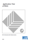
Fieldbus Segment Calculator v3.03 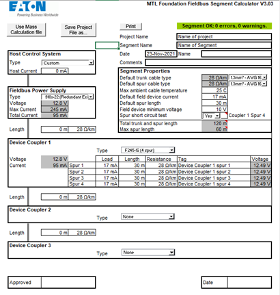
![]()
The MTL Fieldbus Segment Calculator is intended to assist network and planning engineers when designing and implementing FOUNDATION fieldbus ™ H1 networks. It models the behaviour of user-selectable power supplies and device couplers, and provides a rapid “Go/No-Go” indication of the electrical characteristics of the fieldbus network. All the relevant parameters of the fieldbus segment are easily configurable, including field device currents, cable lengths, cable cross-section and number of fieldbus spurs. Power supply, device coupler and host control system types are easily chosen from pull-down menus, or can be user-defined.
The new 3.03 version merges the earlier, separate tools for Fieldbus Barriers and Megablock Device Couplers, and covers the following device types:
- 9180 Series FF general purpose power supplies
- 910x-22 Series redundant FISCO power supplies
- 9122-IS Series simplex FISCO power Supplies
- F100 Series simplex general purpose power supplies
- F800 Series redundant power supplies
- Custom (user selectable) power supplies
- F300 Series Megablock device couplers (general purpose applications)
- F300 Series Megablock device couplers (Ex ic spur applications)
- F200-IS Series intrinsically safe Megablock device couplers
- F200-XE Series Zone 1 Megablock device couplers
- FCS-MBx-SG ‘classic’ Megablock device couplers
- 937x-FB Series Fieldbus Barriers
The calculator uses a spreadsheet-based platform and does not require any executable programme files to be installed on the user’s machine – avoiding the need for special permissions or administrator rights. Parameters can be easily copied and pasted into other software applications or printed as a permanent record of the segment characteristics.
NOTE: Macros must be enabled for the tool to operate
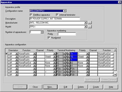
MTL SmartPlant Instrumentation (SPI) symbol library for FOUNDATION fieldbus™ components
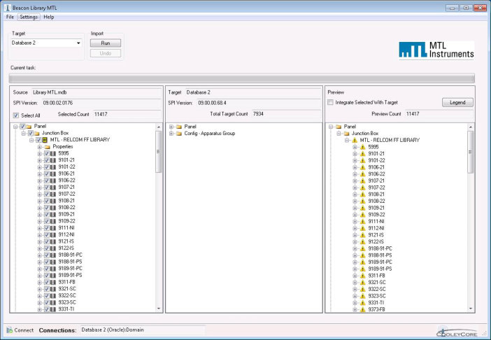
We have made it easier for engineering designers and end users to use their FOUNDATION fieldbus™ products by developing a utility to import the complete range of MTL-Relcom fieldbus products (Power Supplies, Megablocks™, surge protectors,Fieldbus Barriers and Entity conversion blocks) into SmartPlant Instrumentation version 9 and 2009.
This new, updated version of SPI includes all the latest products and ranks among the most successful examples of the new generation design tools created to reduce the cost of designing control systems. The cost of designing a single control loop can be in excess of one man-day, so using tools like SmartPlant can dramatically reduce these costs. The utility, including all associated files is available for download below.
FIELDBUS NETWORK - A fieldbus network interconnects transmitters and actuators to a control system over a single twisted pair cable, providing power and communications for the fieldbus devices. The image above shows key components required to build a fieldbus network.
Hover the mouse over each component to find out more and click image for any further details.
 FOUNDATION fieldbus™ H1 provides an open, nonproprietary fieldbus network for control systems and field instruments. Foundation H1 is intended primarily for process control, field-level interface and device integration. Running at 31.25 kbit/s, the technology interconnects devices such as transmitters and actuators on a field network. H1 is designed to operate on existing twisted pair instrument cabling with power and signal on the same wire and also supports Intrinsically Safe (IS) applications. Each device has its’ own “intelligence” and communicates via an all-digital, serial, two-way communications system. MTL provides a comprehensive range of fieldbus power supplies, wiring components, diagnostic tools and displays for FOUNDATION fieldbus H1 networks.
![]() PROFIBUS PA is the version of PROFIBUS for process industry applications. Running at 31.25 kbit/s, the technology interconnects devices such as transmitters and actuators on a field network. Profibus PA uses twisted pair instrument cabling with power and signal on the same cable and also supports Intrinsically Safe (IS) applications. MTL provides a comprehensive range of power supplies, wiring components, diagnostic tools and displays for Profibus PA networks.
PROFIBUS PA is the version of PROFIBUS for process industry applications. Running at 31.25 kbit/s, the technology interconnects devices such as transmitters and actuators on a field network. Profibus PA uses twisted pair instrument cabling with power and signal on the same cable and also supports Intrinsically Safe (IS) applications. MTL provides a comprehensive range of power supplies, wiring components, diagnostic tools and displays for Profibus PA networks.
Eaton’s MTL product line provides a range of FOUNDATION fieldbus™ devices to support your fieldbus installation including a diagnostic monitoring module and a range of fieldbus displays.
For a copy of the fieldbus SmartPlant Instrumentation (SPI) library ... <click here>
We are no newcomers to the fieldbus environment. From involvement in defining the earliest standards through to representation on today’s industry bodies, MTL and Relcom have attained a distinguished profile in fieldbus technology. And to maximise your efficiencies using our equipment we have produced various software packages designed to help fieldbus engineering.
MTL SmartPlant Instrumentation (SPI) symbol library for FOUNDATION fieldbus™ components![]()
MTL has made it easier for engineering designers and end users to use their FOUNDATION fieldbus™ products by developing a utility to import the complete range of MTL-Relcom fieldbus products (Power Supplies, Megablocks™, surge protectors,Fieldbus Barriers and Entity conversion blocks) into SmartPlant Instrumentation version 9 and 2009.
This new, updated version of SPI includes all the latest products and ranks among the most successful examples of the new generation design tools created to reduce the cost of designing control systems. The cost of designing a single control loop can be in excess of one man-day, so using tools like SmartPlant can dramatically reduce these costs. The utility, including all associated files is available for download below.
9370-FB Series Fieldbus Barrier Segment Calculator v0101![]()
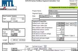
This software calculator tool models the behaviour of MTL’s 9370-FB Series Fieldbus Barriers, and provides a rapid “Go/No-Go” indication of the electrical characteristics of the fieldbus network. All the relevant parameters of the fieldbus segment are easily configurable, including field device currents, cable lengths, cable cross-section and number of fieldbus spurs. Power supply and host control system types are easily selectable from pull-down menus, or can be user-defined.
The calculator uses a spreadsheet-based platform and does not require any executable programme files to be installed on the user’s machine – avoiding the need for special permissions or administrator rights. Parameters can be easily copied and pasted into other software applications or printed as a permanent record of the segment characteristics.
NOTE: Macros must be enabled for the tool to operate.
Fieldbus segment calculator v1.5.4 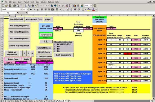
The MTL segment calculator is a spreadsheet-based tool designed to assist network and planning engineers when designing and implementing FOUNDATION fieldbus ™ H1 networks. Specific data covering MTL fieldbus power supplies, including the latest Redundant FISCO units, wiring hubs and third-party field devices are pre-programmed although users can input their own device parameters. Calculations using surge protection devices are also accommodated.
Fieldbus Barrier Segment calculator v1.0.4.0
The MTL Fieldbus Barrier segment calculation software tool is designed for use with the 9311-FB Zone 1 Fieldbus Barrier. The tool automatically checks the design of fieldbus segments using MTL Fieldbus Barriers. Warning messages will be displayed if any of the input or calculated parameters are out of range.
| Q |
Is the change-over ‘bumpless’ ? |
||||||||||||||||||||||||||||||||||||||||||||||||||||||||
| A | Yes. Interruption of fieldbus communications is momentary, and is accommodated by the re-transmission mechanism that is implicit in the Foundation fieldbus protocol. There will therefore be no loss of control, and the plant operator will observe no loss of data. |
||||||||||||||||||||||||||||||||||||||||||||||||||||||||
| < back | |||||||||||||||||||||||||||||||||||||||||||||||||||||||||
| Q |
What’s inside the ‘Supply Arbitration Modules’ ? Are there relays inside? |
||||||||||||||||||||||||||||||||||||||||||||||||||||||||
| A | Each Supply Arbitration Module (SAM) contains electronic circuits to monitor the output of one FISCO power supply, and to switch the output of that power supply to the field segment. The switching is solid-state, so there are no relays. The two modules communicate with each other by ‘handshaking’ to make sure that they can never both be ‘on’ at the same time. | ||||||||||||||||||||||||||||||||||||||||||||||||||||||||
| < back | |||||||||||||||||||||||||||||||||||||||||||||||||||||||||
| Q |
Will the output specification of Redundant FISCO be the same as the existing 912x-IS power supplies? |
||||||||||||||||||||||||||||||||||||||||||||||||||||||||
| A | There will be a slight reduction in available output current and voltage compared with MTL’s existing range of ‘simplex’ power supplies, but this will result only in a small change to the maximum segment length or device loading. | ||||||||||||||||||||||||||||||||||||||||||||||||||||||||
| < back | |||||||||||||||||||||||||||||||||||||||||||||||||||||||||
| Q |
Why are there two Supply Arbitration Modules per fieldbus segment? |
||||||||||||||||||||||||||||||||||||||||||||||||||||||||
| A | To eliminates single points of failure for complete redundancy. If one ‘SAM’ fails, the system continues to provide power to the fieldbus segment. | ||||||||||||||||||||||||||||||||||||||||||||||||||||||||
| < back | |||||||||||||||||||||||||||||||||||||||||||||||||||||||||
| Q |
Does the Redundant FISCO power supply work with existing Intrinsically Safe Megablock wiring hubs, or do they need to be different? |
||||||||||||||||||||||||||||||||||||||||||||||||||||||||
| A | Redundant FISCO works with MTL’s existing range of IS Megablocks (types F245 – F271). | ||||||||||||||||||||||||||||||||||||||||||||||||||||||||
| < back | |||||||||||||||||||||||||||||||||||||||||||||||||||||||||
| Q |
Can the modules be ‘hot-swapped’ to allow replacement of failed modules without losing power or communications? |
||||||||||||||||||||||||||||||||||||||||||||||||||||||||
| A | Yes. The power supply and Supply Arbitration Modules may be easily ‘hot swapped’ without powering down the system, and without causing loss of power or communications. | ||||||||||||||||||||||||||||||||||||||||||||||||||||||||
| Q |
Can the existing 932x-SC Spur Connectors be used to connect to ‘Entity’ certified fieldbus devices, and devices in Zone 0 hazardous areas? |
||||||||||||||||||||||||||||||||||||||||||||||||||||||||
| A | Yes, these can be used on Redundant FISCO segment in exactly the same way as for simplex. | ||||||||||||||||||||||||||||||||||||||||||||||||||||||||
| Q |
Doesn’t the FISCO standard say that there should be only one source of power in a FISCO network, making it impossible to have redundant power supplies? |
||||||||||||||||||||||||||||||||||||||||||||||||||||||||
| A | No. This clause in the IEC60079-27 standard is intended to mean that the maximum values of Uo, Io and Po for the power supply must not be exceeded on any segment, and that the power must be connected at only one point on the bus. MTL’s solution complies with both these requirements because it provides power onto the segment at only one point (at the power supply terminals), and the Uo, Io and Po values for the redundant output will be certified to comply with the maximum values specified for FISCO. | ||||||||||||||||||||||||||||||||||||||||||||||||||||||||
| Q |
What cable lengths can be supported using Redundant FISCO |
||||||||||||||||||||||||||||||||||||||||||||||||||||||||
| A |
|
| Q |
Do I have HART capability with Analog Modules ? |
| A |
Analogue I/O modules are available both with & without HART capability.
Analog Output (AO) modules:
|
| < back | |
| Q |
Can I multidrop a number of HART devices on a single analog channel ? |
| A | Only a single HART field device per channel is supported in both the Analog Input & Output I/O modules. The RAM memory that is available in each I/O module has to support the handling of up to 4 HART variables and HART status for each connected HART device, covering all eight I/O channels. Attempting to multidrop devices on each channel would result in severe design constraints. .Also, once multiple devices are connected to a single channel the basic 4-20 mA signal is lost, data transfer reverting to purely a HART polling technique. This would have a detrimental effect on data transfer rates, and in most circumstances would be unacceptable. For this reason support of multiple instruments on a single channel is not available. |
| < back | |
| Q |
How do I connect Instrument Maintenance Management software to the MTL8000 1/1 |
| A | The MTL8000 1/1 system supports use of the Profibus DP.V1 protocol, whereby a Master Class 2 host may be accommodated on the Profibus network. For this purpose a Class 2 Master, running Instrument Management software, facilitates HART bi-directional pass-through transactions to all connected HART field instruments. This enables the full use of such maintenance facilitates over the main Profibus highway, together with the main process control communications running from a Master Class 1 host. |
| < back | |
| Q |
What HART solutions can MTL provide? |
| A | Refer to the HART section of Website. |
| < back | |
| Q |
When I have a HART transmitter, can I connect a hand held terminal in the field? |
| A | A hand-held terminal can be connected at the HART field instrument itself or at the field terminal to which the instrument is connected. If the application involves hazardous areas then the user must ensure that appropriate certification exists for the hand-held device being used. |
| Q |
What is Dual-LAN operation with HART Maintenance? |
| A | This application was created to allow the use of redundant Modbus communication over dual LAN highways, to multiple MTL8000 nodes, whilst allowing for HART interfacing via the local configuration port of the Bus Interface Module (BIM). |
| Q |
What is meant by General Purpose, 2/2 and 2/1 I/O? |
| A | General Purpose I/O This is for use in process industry applications where there is no risk of explosion. In traditional IS terminology these applications would be called “Safe” - in contrast to those areas which do have a risk of explosion. Many process operators and specifiers, however, would consider these to be far from safe; for example, they may be hot, heavy, toxic or corrosive and, therefore, viewed as dangerous. It is therefore inappropriate to use the traditional IS terminology of “Safe Area” I/O and the term General Purpose has been adopted. General Purpose Field Terminals allow any I/O Module to be inserted in to any Field Terminal, once the “Module Type” key has been re-positioned by the User. However, General Purpose Modules cannot be inserted in to any Field Terminal other than the “General Purpose” type. 2/2 I/O The “2/2” product is I/O for mounting in North American Division 2 or CENELEC Zone 2, with field wiring connected to devices in the same Division or Zone - hence “2/2”. The I/O Modules are actually identical to “General Purpose” I/O Modules - but the relevant Field Terminal uses a different key position. The use of two names for the same product is to position it correctly for two similar, but different Users.The “2/2” Field Terminals have a key which is coded so as to ensure that Field Terminals intended for use with Non-Incendive I/O Modules cannot be used with I/O Modules for Non-Arcing field connections, and vice versa. 2/1 I/O The “2/1” product is for mounting in Division 2 or Zone 2, with field wiring connections to devices locatedd in Division 1 or Zone 1 / Zone 0 hazardous areas. The “2/1” Field Terminals are coloured blue (for Intrinsic Safety) and are keyed such that it is not possible to insert an I/O Module which carries General Purpose or “2/2” keying in to a “2/1” Field Terminal. |
| < back | |
| Q |
Can I use the standard MTL Remote I/O product in a European Zone 2 ? |
| A | MTL8000 General Purpose I/O can be used in Zone 2 applications, under the terms of ‘ATEX’ Directive 94/9/EC. The product is marked as suitable for Zone 2 in accordance with the Directive and carries the CE and Epsilon-x marks. Under the Directive, MTL issues its own apparatus certificates and Code of Practice for installation and maintenance. |
| < back | |
| Q |
What restrictions are there on hot-swapping of modules in Zone 2 / Div 2 ? |
| A | Non-IS MTL8000 system For the MTL8000 Non-IS system, I/O modules can be hot-swapped in Division 2 or Zone 2 hazardous areas provided the following conditions are met: Where a module uses Bussed Field Power, this must first be de-energised before removing or replacing the module. If the isolating switch is itself within the Division 2 or Zone 2, it must be an appropriately (Ex) explosion protected type. I/O modules in this category are: > All module-powered DI and DO versions (AC and DC) > AI, 4-20mA with/without HART > AO, 4-20mA with/without HART > Pulse/Frequency Input module (MTL8123) Where a module receives an input which is sourced from the field, the field power supply must first be de-energised before removing or replacing the module. I/O modules in this category are: > All sinking DI versions (AC and DC) > All un powered DO versions (AC and DC) > Pulse/Frequency Input module (MTL8123) (certain field devices) The node must be powered by MTL’s own power supply module or modules (ie, type MTL8910-PS-DC, MTL8913-PS-AC, MTL8914-PS-AC). Users wishing to use other types of power supply connected to the external power supply terminals on the MTL8000 carriers should consult the Technical Support department since use of such equipment is not specifically covered by the Factory Mutual approvals. When the above conditions are met, the 12V system power energising the carrier ‘Railbus’ operation does not need to be de-energised before hot-swapping is attempted. The node can therefore continue to operate.Note : the user chooses at what point to provide the necessary isolating switches for Bussed Field Power; if a single switch is used in the BFP feed to a large number of modules, then all these modules will lose their power when hot-swapping is undertaken. Individual switches can be used in the feed to pairs of modules if it is required to take the fewest channels out of service. IS MTL8000 system All I/O modules offering an intrinsically safe interface may be hot-swapped in a Zone 2 or Division 2 hazardous area, with the internal 12V Railbus supply energised. Since Bussed Field Power is not used, there are no restrictions, or requirements, for local isolation before removing or replacing a module. The Railbus Isolator may also be hot-swapped, but the power supply modules (type 8920-PS-DC) must be de-energised before they are replaced. |
| < back | |
| Q |
How do I tell which modules can be live worked ? |
| A | The list of 2/2 modules which are non-incendive for which the field circuits can be live worked in a Division 2 and Zone 2 application is as below: 1. 8101-HI-TX * (Analogue Input Module with HART) 2. 8104-AO-IP * (Analogue Output Module) 3. 8105-TI-TC (Thermocouple Input Module) 4. 8106-TI-RT (RTD Input Module) 5. 8110-DI-DC * (Non Isolated Digital Input Module) * Note that the use of Bussed Field Power supplies may prevent removal of the modules whilst this power source is live. The 2/2 data sheets for the above modules indicate the special field terminal required to be used for application in Division 2 or Zone 2 area. This terminal will ensure that accidental interchange with other modules does not take place. All other 2/2 modules are Non-Arcing and cannot be live worked in Division 2 or Zone 2 Hazardous Areas. Seperate marking is given on the module to indicate whether it is Non-Incendive or Non-Arcing. A definitive description of the types of circuit and permitted live-working practice is clearly documented in the AN8001 Code of Installation Practice. |
| < back | |
| Q |
If the system is installed in Div 2 or Zone 2 is it normally non arcing or non-incendive ? |
| A |
Some parts of the installation are Non-Arcing and some are Non-Incendive, depending on the levels of voltage and current present at the individual connections. In general, all power supply connections (including Bussed Field Power) are non-arcing because the amount of energy in these circuits is not controlled and is therefore capable of causing ignition. (Note that the term ‘Non-Arcing’ implies that the circuits are not permitted to produce an arc or spark when operating normally, since this could be capable of igniting the gas.)
|
| Q |
Can I connect a 2/1 module next to a 2/2 module ? |
| A | Railbus Isolator forms an integral part of an MTL8000 system structure where intrinsically safe interfaces are required, and interconnects the Non-IS and IS sections of the system. It limits the level of energy available to the IS interface section of the system, but also provides the inherent requirement of a 50 mm physical seperation between Non-IS and IS circuitry. It is not possible to omit the Railbus Isolator device when building up such an IS system due to the physical arrangement of the carriers employed. Hence, 2/2 and 2/1 modules can only be mounted on either side of the Railbus Isolator. |
| Q |
Can IS and non-IS be mixed on the same node? |
| A | Non-IS and IS modules can share the same MTL8000 node. A Railbus Isolator forms an integral part of an MTL8000 system structure where intrinsically safe interfaces are required, and interconnects the Non-IS and IS sections of the system. It limits the level of energy available to the IS interface section of the system, but also provides the inherent requirement of a 50 mm physical seperation between Non-IS and IS circuitry. It is not possible to omit the Railbus Isolator device when building up such an IS system due to the physical arrangement of the carriers employed. Hence, 2/2 and 2/1 modules can only be mounted on either side of the Railbus Isolator. The ability to mix the types of protection for field devices is particularly useful for customers who use, eg, IS transmitters and Flameproof (Explosion proof) valves. |
| < back | |
| Q |
What isolating switches must be used in Zone 2 ? |
|
For an MTL8000 enclosure located in Zone 2, any isolating switches in the power supply circuits must be Ex certified, to avoid any ignition risk.
It also applies to the Bussed Field Power circuits. If the user requires to “hot-swap” I/O modules where the Bussed Field Power supply creates a Non-Arcing environment, then the BFP must be isolated first. |
|
| < back |
| Q |
What does G3/G2 mean? |
| A | G2 and G3 are corrosion resistance classifications within the ISA standard S71.04. The ‘G’ denotes attack by gaseous air-borne pollutants and the number the level of contamination. G2 is defined by the standard as: “Moderate - An environment in which the effects of corrosion are measurable and may be a factor in determining equipment reliability”. G3 is defined by the standard as: “Harsh - An environment in which there is a high probability that corrosive attack will occur. These harsh levels should prompt further evaluation resulting in environmental controls or specially designed and packaged equipment.” MTL8000 is designed for use in G3 environments providing the installation instructions are followed carefully. |
| < back | |
| Q |
What degree of corrosion resistance can the MTL8000 equipment withstand |
| A | An indication of this can be achieved by exposure of the MTL8000 to Ammonia gas. The ISA G3 corrosion test included exposure to ammonia at a concentration of 25 parts per million for a continuous period of 30 days. The MTL8000 equipment achieved the G3 rating, as can be scrutinised by reference to the testing carried out by the British Standards Institute. Note that the testing was done without the equipment being mounted in an enclosure (ie, direct pollution of the modules and carriers). Hence, this is equivalent to a much longer installed lifetime within a cabinet, with occasional exposure to the gas due to opening of the enclosure door, or seepage at lower concentration into the enclosure. |
| < back | |
| Q |
Why should I use MTL8000 instead of a PLC and remote I/O? |
| A |
It has been well proven in factory automation that mounting the PLC I/O close to the process reduces installed cost. It has not been possible for the Process industries to enjoy that same level of installed cost reduction because PLC I/O does not provide the necessary capability. It does not provide the environmental performance or the functional specifications, nor does it provide for hazardous areas installation & interface to standard Process Industry Smart instrumentation (such as HART transmitters).
|
| < back | |
| Q |
Is the -40°C to +70°C valid for horizontal and vertical mounting ? |
| A | The full -40°C to +70°C specified operating ambient range is achieved when the Carrier is mounted horizontally, with the Field Terminals below the I/O Modules. When the Carrier is mounted vertically, with the Field Terminals to either side of the I/O Modules, the operating ambient range is -40°C to +55°C |
| < back | |
| Q |
Can the MTL8000 2/x system be used in areas with dust hazards ? |
| A | The MTL8000 has been designed in accordance with the ATEX directives 94/9/EC (Apparatus Directive 100a) for installation within gas groups in acordance with directive 1999/92/EC (Workplace Directive 137). It is not marked for dust hazards (D) although it is possible to comply with the appropriate directives by evaluating the dust in question and the specific application. A generic letter is attached, for use within any ATEX compliant region, for any application that focuses on dust hazards, and demonstrates how MTL8000 may be located in Zone 22 without further certification (equivalent to Zone 2 for gases). The hardware would be supplied by MTL with an appropriate letter detailing compliance. MTL would have to quote a documentation charge in line with the work required to complete any evaluation. It is suggested that any request for quotation for dust applications is passed to the MTL8000 Product Manager to obtain an appropriate charge. |
| Q |
What does the Railbus Isolator do? |
| A |
The Railbus Isolator plays an important part in protecting the IS field connections of MTL8000 2/1 I/O modules (i.e. modules which have IS field wiring). It provides a barrier against the invasion of voltages up to 250V. Conventionally, such a barrier tends to be placed in individual I/O modules, but the additional components and the necessary clearance distances would have restricted the number of channels in a module. This innovative alternative design was to place the isolation in the supply rail, i.e. the Railbus. This provides full 250V Um protection for all of the IS modules, not only against invasion from power supply but also local area network faults. An additional benefit is that it reduces the hardware cost per channel and maintains the same channel density as found in 2/2 systems. |
| < back |
| Q |
What field terminals are used for THC and RTD modules in Zone 2 / Div 2 applications? |
| A | MTL8605-FT-TC & MTL8606-FT-RT field terminal blocks are keyed as ‘Non-Incendive’ types since THC and RTD field circuits are inherently non-incendive. They can therefore be used in applications where the field wiring enters Zone 2 / Div 2, as well as safe area applications. The reason there are Non-Incendive and Non-Arcing versions of other field terminals is to allow the user to avoid unnecessary complication by selecting the standard type in non-hazardous applications regardless of whether the module is non-incendive or non-arcing. Note that for intrinsic safety applications the terminal blocks would be : THC MTL8625-FT-IS RTD MTL8626-FT-IS |
| < back | |
| Q |
Do the field terminals for IS modules have the barrier in them? |
| A | No. All Hazardous Area protection circuitry is within the I/O Module. This allows all Field Terminals to contain only passive components. (Some Systems Integrators and Users specify that the level of qualification required to install components containing active circuitry is higher than that to install passive components. The MTL8000 Series allows all wiring connections to be made to passive system components, with active system components being pushed home and secured with a single retaining screw). |
| < back | |
| Q |
I can not read the terminal number on a terminal block when it is installed? |
| A | The Field Terminals have moulded-in terminal identification numbers (1-16) which can normally be seen during installation. If the position of the cable or conduit is such that the numbers cannot be seen clearly, the Field Terminal Tag Strip can be used to more clearly indicate the terminal identification numbers. (The Tag Strip has odd numbered identification numbers moulded in to it at an angle to those moulded in to the Field Terminal itself). |
| < back | |
| Q |
Are cage clamp terminal blocks available ? |
| A | The design of the MTL8000 Field Terminals allows for a number of different wiring connection methods which include cage clamp and multi-pole connector style. The MTL8000 2/2 system currently uses multi-pole connectors as standard, whilst the MTL8000 1/1 system uses a cage clamp approach. |
| < back | |
| Q |
Why are there separate ‘Safe Area’, ‘Non-Incendive’ and ‘Non-Arcing’ field terminals |
| A | In Zone 2 & Division 2 applications (ie, where the field wiring from an MTL8000 I/O module enters a Zone 2 or Div 2 hazardous area), the certification authorities require that incendive voltage and current levels must not enter the hazardous area due to accidental interchange of I/O modules - ie by plugging the wrong module type into an existing installed field terminal. Hazardous area wiring Zone 2 and Division 2 circuits fall into one of two types: ‘Non-incendive’ circuits, which carry only low levels of voltage and current because they are ‘energy-limited’ within the field circuit. These circuits can be live-worked in a similar way to intrinsically safe circuits. ‘Non-arcing’ circuits, which carry high levels of voltage and current, and which must not be live-worked in the hazardous area. Their safety is ensured by not allowing arcs or sparks to be produced, usually by means of mechanical protection of wiring and by eliminating unprotected contacts. With the MTL8000, the type of field circuit (ie ‘non-incendive’ or ‘non-arcing’) is often defined by the I/O module type. For example, 4-20mA AI & AO modules have non-incendive field circuits, whereas AC & DC DO modules typically involve ‘non-arcing’ circuits. The published MTL8000 data sheets show which type of field wiring each I/O module type has, accompanied by the recommended field terminal type. The certification requirement is that the MTL8000’s keying system should prevent an I/O module with non-aring field circuits from being plugged onto a field terminal belonging to an I/O module with non-incendive field circuits. This situation could present an unsafe condition. Non-incendive modules are therefore keyed differently from non-arcing modules, so that they will only plug into the appropriate type of field terminal. A diagram of the different field terminal keys is illustrated in the MTL8000 Installation Guide, document reference INM8000. Hence the correct type of either Non-Incendive and Non-Arcing field terminals must be selected for Zone 2 and Division 2 applications. Safe area wiring In applications where the field wiring is located in a safe area only, the certification requirements do not apply, and there is no necessity to differentiate between Non-Incendive and Non-Arcing wiring. The selection and use of the different types of field terminal would be an unnecessary complication, so a ‘safe area’ variant of field terminal may be selected. The safe area field terminals (available in fused and unfused versions) will support the use of Non-Incendive or Non-Arcing modules. Exceptions Some field terminal types (eg, for RTDs, thermocouples and typically 4-wire transmitters) are not available in seperate ‘safe area’ and ‘hazardous area’ variants, since they are always keyed according to whether they are non-incendive or non-arcing. This type is used even in safe area applications. |
| Q |
What functionality can a terminal block have, IS protection, signal conditioning etc.? |
| A | The Field Terminal provides screw clamp connectors for field wiring and offers optional fusing and loop disconnection. All signal conditioning and Hazardous Area protection circuitry is within the I/O Module itself, not in the Field Terminal. The exception to this is the cold junction compensation sensor for Thermocouple Input Modules, which must be sited as close as possible to the connection point of the thermocouple compensation cable (the cold junction), and is therefore mounted within the field terminal itself. |
| Q |
Do 2/2 DI modules need fused field terminals ? |
| A |
Fused terminals can be used for all Digital Inputs. The fuse provides two functions:
Examples are : |
| Q |
What is the advantage of having seperate, removable, field terminals? |
| A | Using separate, removable field terminals provides a number of advantages: 1. The principle advantage is the ability to make field wiring connections independent of the I/O Module. This allows the wiring connection to be done quickly and easily - by removing the Field Terminal from the Carrier, and then making the wiring connections holding the Field Terminal in one hand and screwing down the terminal clamps with the other. Any mistakes that are made in wiring the connectors—e.g. misalignment of the wire or crimp, leaving stray strands etc.—are then easily seen. 2. If the module needs to be changed, the wiring stays in place, ensuring that the original wiring is maintained and mistakes in rewiring are avoided. 3. If any of the Field Terminals become damaged through rough handling they can be easily replaced. |
| Q |
Is there cable size recommendation for the LAN connection? |
| A | The Screw type LAN interface connections are detailed in the Node Services Carrier data sheets and the Installation Manual. The cable size of screened twisted pair cable which can be accepted by the screw terminals is as under : 1. For single stranded wires the terminal can accept any size between 0.14 mm to 4 mm conductor with a nominal size of 2.5 mm. 2. For multi stranded wires the terminal can accept 0.14 mm to 2.5 mm conductor. Typically, for such applications, and depending on distance, a twisted pair cable of 22AWG and 150ohm / km resistance is selected corresponding to a Belden cable type 9182. This is typical, the choice depending on the distance to the host and the speed of the LAN selected. The level of mechanical protection (eg steel wire armour or resilient plastic sheath) would generally be determined by the requirements of local site standards and their codes of practice. |
| Q |
Do all Field Terminals have fusing? |
| A | Field Terminals for General Purpose I/O Modules are available in Standard (unfused), Fused, Thermocouple & RTD versions. The data sheets for each I/O Module recommend the type of Field Terminal that should be used with that module, perhaps also qualifying its use. Fusing is not required where the maximum short circuit current can be handled by the electronic protection within the I/O Module itself, or where fusing would normally be sited close to the field instrument. An example of the latter is the Isolated Discrete Input Module, which is powered by an external supply to the field instrument, and which should be fused close to the power supply itself. |
| Q |
Why do analogue modules have no isolation between channels? |
| A | Because they are all connected to the same Bussed Field Power supply. |
| < back | |
| Q |
For Non-IS (2/2) Temperature I/O modules, what does “15-bit plus sign” mean ? |
| A |
This refers to the resolution of the analog-to-digital converter within the module. The resolution is 15 bits - with a further bit reserved to indicate whether the value is positive or negative. Deduced from 2(15) = 32,768. With 15 binary bits available to relate the (absolute) value of an Analogue signal, the value can be in a range : -32768 to +32767. The Most Significant “sign” Bit is used to indicate whether the signal is positive or negative. |
| < back | |
| Q |
How do I handle frequency / counting inputs ? |
| A |
The DC Digital Input Modules feature limited pulse counting capabilities, targeted as event counters. MTL8123 Non-IS (2/2) I/O module These can count at up to 50 kbit/s. |
| < back | |
| Q |
Can I swap modules while powered? |
| A |
The MTL8000 System Railbus has been specifically designed to allow I/O Modules and BIMs to be removed and replaced without the need to remove the System Power Supply in both General Purpose and in Division 2/ Zone 2 Hazardous Area applications. |
| < back | |
| Q |
What is the input impedance of the 8201-HI-IS analogue input module? |
| A |
The specification of 15V @ 20mA available for a field transmitter already accounts for the I/O module impedance. The Input impedance is approximately 350ohms, being the sum of the safety resistor, a sense resistor, and various current limiting components. |
| Q |
8104-AO-IP Analog Output Module - Ripple & Quiescent Current |
| A |
The following is the relevant data for the 8104-AO-IP : The output ripple is 0.02% of Full scale. The quiescent current for the module, ie, the current drawn from the Bussed Field Power when all outputs are disconnected is 60mA. |
| Q |
What is the output resolution for an Analog Output (AO) module? |
| A |
12 bit resolution. This provides a range of 4,096 2(12). The electronic range of the AO module is 24 mA, resulting in a signal resolution of 1 bit = 24 / 4096 = 6 uA. |
| Q |
Can a Thermocouple I/O module be used with Grounded Thermocouples ? |
| A | Thermocouple input modules can be used with grounded thermocouples. |
| Q |
Do I need keying for general purpose modules? |
| A |
The keying arrangement on the MTL8000 Series achieves two objectives: 1) It prevents insertion of General Purpose I/O Modules in to Field Terminals connected to Hazardous Area wiring; ensuring that the User can only use appropriately protected combinations of I/O modules and Field Terminals. 2) It prevents accidental insertion of I/O Modules into a Field Terminal which has previously been keyed for an I/O Module of a different type. |
| Q |
What happens if an I/O module is placed in the wrong position? |
| A | The keying system between I/O Modules and Field Terminals prevents I/O Modules from being inserted in to the wrong position. If the keying system is somehow defeated into allowing an I/O Module of a different functional type to be used, the BIM will recognise the module type has been changed and cease any process data transactions with that module position. The BIM will not attempt any output drive to an incorrect module. |
| Q |
What happens if I add another module to a vacant slot on the carrier ? |
| A | MTL8000 2/x Modbus system: Since the module is not part of the current configuration, the BIM will not conduct transactions to this module. The BIM will only commence reading / writing to the module once the configuration is changed. In the meantime the module will show a flashing (red) fault LED to show that it is not configured. The user must employ the configurator tool to modify the node content, adding the new module with its channel attributes, and download the new file version. Once the downloaded file complies with the hardware in place, communication commences with the additional module and two-way data transactions may occur. MTL8000 2/x Profibus system: If a new module is inserted, and the host is somehow initialised into its configuration process prior to changing the configuration content, then communication with that slave will cease. This could occur by, eg, a temporary break in the LAN being restored. The configuration for that node must be modified, and the host initialised, to initiate the revised configuration process for successful operation to occur. MTL8000 1/1 Profibus system: If a new module is inserted communication with that slave will cease since an incompatibility is immediately flagged. The configuration for that node must be modified, and the host initialised, to initiate the revised configuration process for successful operation to occur. |
| Q |
How do I get status information about modules ? |
| A | The Bus Interface Module (BIM) scans all I/O modules to retrieve status information. By host program, this status information can be continuously read by the host device. |
| Q |
What Fieldbus protocols are available with MTL Remote I/O ? |
| A | The MTL8000 system has an open architecture which allows it to support a number of different open fieldbus protocols by means of different Bus Interface Modules (BIMs). Modbus : released in November 1997 Profibus-DP : released in October 1998 Ethernet : released in July 2003 |
| < Back | |
| Q |
What is the maximum cable length for the configuration tool? |
| A | The local port of the BIM employs a standard RS232 connection, hence the cable limitation is 15m (50 feet). Note that when using a Modbus BIM it is possible to configure the node remotely via the second LAN highway. Since this is a standard RS485/422 connection the cable length limit will be 1200 metres. |
| < Back | |
| Q |
How are Analog values reported? |
| A | Data values for both Input & Output Analogue variables are handled in the BIM as 16-bit Unsigned Integer values, giving a range of 0 through 65535. This range is applied to an electronic current range of zero through 25 mA. Communication between the Host and the BIM involves raw data within the range/s described. The host then interprets the analog value as engineering units representing the process value/s. |
| < Back | |
| Q |
What is an API? |
| A | An API (Application Programmers Interface) is a piece of software that translates hardware information into a form that can be more easily understood by the user application. It is ‘the filling in a sandwich’. On one side is the user application—user friendly, and user orientated—on the other side is the hardware—often unfriendly and spoken to in engineering terms. An API between these two enables a User to successfully communicate with the hardware. In the case of MTL8000, the API library of commands would be required by any user who wishes to produce a BIM Gateway that interfaces to a non-standard LAN protocol. |
| < Back | |
| Q |
Choice of Node Services Carrier to be used for the Modbus, Profibus-DP, or MOST Controller BIM? |
| A | A choice of carriers are available for mounting the Bus Interface Module (BIM), dependent on the exact system architecture required. The reader is referred to the standard document below, noting the Node Services Carrier numbers : 8711-CA-NS Node Services Module - Modbus 8712-CA-NS Node Services Module - Profibus 8715-CA-BI Universal BIM Carrier 8718-CA-NS Node Services Module - Node Services Module 8750-CA-NS Controller / eBIM Carrier |
| Q |
How does a BIM react to a change in module type, perhaps through a mistake made during maintenance? |
| A | If the type of module inserted in a specific carrier slot location is changed it has to be accompanied by the user changing the configuration data held by the BIM. If the I/O Module is different from the type expected by the BIM’s configuration, the BIM will not allow any data transactions, neither input or output, to occur. The keying system between I/O Modules and Field Terminal Blocks ensure that it is not possible to accidentally replace an I/O Module of one type with a different Module; the user must take positive action to change the Field Terminal Block keying to match an I/O Module type. Once the Field Terminal keys have been adjusted, the new I/O Module may be inserted. Once connected to the Railbus, the BIM will detect that the I/O Module has been replaced and will establish its I/O type, but will not communicate with the new module, if different to the previous device, until configured to do so. |
| Q |
What data rates can we select for Modbus? |
| A | Data rates up to 115.2 kbaud can be selected for the MTL8000 Modbus BIM. When used with redundant LAN communication the maximum data rate is 19.2 kbauds. |
| Q |
How many Modbus nodes can be supported on a single network ? |
| A | Modbus will support up to 247 slaves. However, the RS485 physical layer will only support 32 device loads. The network can be extended above 32 by the use of repeaters. Repeaters may be used to increase the number of deviceson the network, or equally to extend the network length. |
| Q |
Can I have dual Modbus connections ? |
| A | The MTL8000 series is designed for Redundant Modbus LAN connections to each Node. It is possible to connect the two LANs to a host with redundant connections, or to two different hosts. By default the slave address applied to both LANs is identical, but they may be selected, using the Configurator, to independent values. |
| Q |
What data rates can be selected for Profibus-DP ? |
| A | Data rates up to 12 Mbits/s are defined in the Profibus standard, whilst operating speeds up to 6 Mbit/s are supported by the MTL8000 2/x Profibus BIM. The DP network of the MTL8000 1/1 system, being intrinsically safe, has a network data rate limit of 1.5 Mbit/s. The maximum cable length decreases as the data rate increases. The use of stub lines along the network should be avoided where speeds exceed 1.5 Mbits/s. |
| Q |
What is the Hamming Distance in Profibus networks? |
| A | The Hamming Distance is a measure of how secure a protocol is against misinterpretation of a packet with errors as a different legal packet. The ‘packet’ in this context refers to a standard Profibus telegram (data frame). Profibus offers a figure of HD=4, indicating that at least 4 bits have to be wrong, and still match the checksum calculations, in order to be mistaken as another valid packet. This integrity is achieved by a combination of each character in a telegram containing an Even parity check, plus an appended ‘Frame Check Sequence’ character at the end of each Profibus telegram. |
| Q |
Can I locate the BIM in one cabinet and some I/O-modules in a second one? |
| A | The MTL8000 may be used in such a configuration. Extension cables are available as a standard feature of the MTL8000. The restriction is that the total length of such a system layout should not exceed 6.5 metres. |
| Q |
What is the maximum distance from the BIM to the last I/O module using extension cables? |
| A | The maximum distance over which the Railbus can communicate is 6.5m. A maximum of 3 Extension Cables may be used on any one node. Each Extension Cable will require a pair of Carrier Extenders - one for the right-hand end of the ‘feeding’ carrier, the other for the left-hand end of the ‘fed’ carrier. Different cable lengths are available. |
| Q |
Do I lose all data when I swap the BIM? |
| A | A BIM stores its configuration file in Non-Volatile memory (flash EPROM), and hence each time the power is cycled its first subsequent action is to configure all its connected I/O modules into the required state. However, if a new un-configured BIM is introduced, an alternative method of configuring is available using the Node Services Module 8510-MO-NS. This device stores a BIM configuration in non-volatile memory. As the new BIM is installed on the carrier it will automatically upload the configuration from the Node Services Module. This is a very efficient means of replacing the BIM device without pre-configuration. The validity of the configuration data is checked by the BIM before use and if it is found to be corrupt then the BIM would not upload it. |
Process I/O products have their own range of frequently asked questions. Try the following table for an answer to your question before contacting MTL directly. |
|
| Product type |
Topics Covered |
| BIM | Bus Interface Modules: Modbus, Profibus-DP |
| IO modules |
Analog and Digital module queries |
| Process I/O HART |
HART in process I/O |
| Field terminals | Terminal types and uses |
| Power Supplies |
The types of power supply and their uses |
| Railbus isolator |
Using the Railbus Isolator for IS applications |
| Environmental specs |
Which environments can the product handle |
| Hazardous areas |
Choosing a product to suit the area |
| Q |
What is SIL? |
| A | Safety Instrumented Systems (SIS) are not a new concept and it has long been the practice to fit protective systems to industrial process plant where there is a potential threat to life or the environment should something go wrong. What is new is that IEC61508 provides guidelines to achieving an adequate Safety Integrity Level (SIL) for systems, sub-systems and components. This international standard defines four Safety Integrity Levels: SIL 1 to 4 each corresponding to a range of target likelihood of failures of a safety function. For further information click here to obtain a copy of the MTL Application Note: AN9025 ‘An Introduction to Functional Safety and IEC61508’. |
| < back | |
| Q |
What is IEC61508? |
| A | IEC 61508 is a ‘generic’ standard, intended to satisfy the needs of all industry sectors. It is a large document, consisting of seven parts and a total of about 400 pages. Ideally it should be used as the basis for writing more specific (e.g. sector- specific and application-specific) standards, but it is also intended to be used directly where these do not exist. It has become a requirement of many customers, and its principles are perceived as defining much of what is considered to be good safety-management practice.
|
| < back |
| Q |
What is the minimum Bussed Power value to power a field transmitter ? |
| A | The Bussed Field Power for a 4-20mA Analog Input (AI) module is specified as requiring 24V DC ±10%, which will provide a minimum of 13.5V DC to a field transmitter. |
| < back | |
| Q |
Can I have redundant power supplies ? |
| A |
Yes. The supply modules powering the system and the bussed field power may be duplicated for redundancy, thus maintaining system operation during failure of any given supply. When using DC power sources, two identical DC supply modules (8910-PS-DC) can be fitted on the 8711-CA-NS or 8712-CA-NS ‘Node Services’ Carrier. Alternatively, if the BIM is mounted on an 8718-CA-NS Node Services carrier, 8910 modules may be mounted on 8717-CA-PS carriers adjacent to the 8718. For AC mains-powered nodes two 8913-PS-AC power supplies can be connected in redundant mode to the 8715-CA-BI Universal Carrier or 8718-CA-NS Node Services carrier. The latter carrier also has inputs for power fail signals from the 8913-PS-AC / 8914-PS-AC, and when fitted with the 8510-MO-NS, detects any power supply failure. This failure may then be transmitted to the host system such that corrective action be taken. Redundant supplies for Bussed Field Power can also be provided by the 8914-PS-AC. For further details on supplying redundant power see Instruction Manual INM8900 |
| < back | |
| Q |
Do I need a power supply for 24V DC ? |
| A |
When an MTL system is required to supply 24V DC to a field instrument, then a 24Vdc supply is required. This ‘Field Power’ is distributed to the individual modules via their carrier and is termed ‘Bussed Field Power’. Note that this applies only to Non-IS applications; the IS portion of any node utilises dedicated power units (8920-PS-DC). |
| < back | |
| Q |
How does power supply redundancy work for 2/1 systems? |
| A |
I/O module power supplies (type 8920-PS-DC) for the 2/1 system provide 12V DC power for (2/1) IS - I/O modules and their field wiring. One power supply will typically power eight 2/1 I/O modules. If the system requires more than one 12V power supply, additional 8920 PSUs are inserted in the line of carriers, thus providing additional current capacity onto the Railbus supplying the I/O modules. For redundancy, one extra 8920 PSU can be inserted in the system. This will provide the necessary power to continue full operation if one of the other 8920 supplies should fail. The failure of the power supply is signalled to the BIM so that replacement can be carried out as soon as possible. |
| < back | |
| Q |
What output power surge is available from the MTL8913 / 8914 |
| A |
The MTL8913 & MTL8914 power supplies can deliver 150% of the output rating for a maximum of 1 second. Both units function with 85– 264 V AC input voltage and may be mounted in Zone 2 / Div 2. |
| Q |
Why is isolation required in fieldbus power conditioners |
| A |
Maintaining isolation between the Fieldbus pair and plant ground is critical to the reliability of FOUNDATION fieldbus™ systems. Isolation has been a requirement of FOUNDATION fieldbus™ since its inception. It was written into the ISA S50.02 standard and later adopted into the IEC 61158-2 standard. The primary reason for this was to reduce the chance of an outside electrical interference affecting the FOUNDATION fieldbus™ signals. As we have gained field experience, it has become apparent that there are other issues that can adversely affect a FOUNDATION fieldbus™ system when isolation is lost. |
| < back |
| Q |
How does FNICO differ from conventional non-incendive practice |
|||
| A | Conventional Non-incendive practice does require cable parameters to be calculated, and the voltage and current values of apparatus to be matched. In the case of North American approvals, the V, I , C and L values are stated in the ‘non-incendive field wiring parameters’, which are part of the approvals listing. The same principle exists for energy-limited approvals for EN 50021, which carry the approvals code EEx n L. This is just like Intrinsic Safety, but note that some North-Amarican NI approvals do not allow live working on the wiring at all, in which case no non-incendive parameters are published. FNICO is like FISCO in that it eliminates the need to calculate cable parameters, provided the cable complies with a minimum requirement (which is the same as that for FISCO). As far as matching power supplies to field instruments is concerned, FNICO requires only that the voltage values are compatible, and in this case the Vmax for the field device can be taken either from its NI approvals or (if no NI approval is stated) from the Intrinsic Safety approvals. The overall result is that FNICO systems are as easy to design as FISCO, but with the benefit of more field devices per trunk due to the relaxed factor of safety for Division 2 apparatus. |
|||
| < back | ||||
| Q |
To what extent can we trust the stated FNICO parameters |
|||
| A | FNICO stays within the boundaries of the experimental work done by PTB for FISCO, so additional testing is not required to prove the safety of FNICO systems. The figures proposed for the MTL FNICO power supplies have been further confirmed by BASEEFA when testing the FISCO units. The FNICO model removes the 1.5 safety factor on current required by the IS standard, and replaces this with the 1.1 factor required by the North American standards, but apart from this no other parameters (including cable parameters) have been modified. MTL is in the process of writing appropriate apparatus and systems standards, together with a code of practice. Longer term, these documents are the basis for a more formal standard and endorsement by the appropriate approvals bodies. |
|||
| < back | ||||
| Q |
What is the status of the FNICO standard? |
|||
| A | The FNICO Technical Specification, in the form of a draft document, has been circulated for comment to PTB in Germany, Baseefa2001 in the UK and Factory Mutual in the US. The initial reaction has been positive in that no technical objections have been raised. FNICO, and the application of FISCO principles to fieldbus applications in Zone 2, were discussed at the IEC SC 31G Intrinsic Safety committee meeting in Dubrovnik, 7-11 April 2003. At the same meeting, it was provisionally agreed that the energy-limited protection technique (Ex nL) for Zone 2 will be transferred from the existing Ex n committee into the intrinsic safety committee. This will give the non-incendive technique, and FNICO itself, a stronger position than at present, with the possible eventual adoption as ‘Ex ic’. If this goes ahead, then it looks probable that FNICO will gain IEC recognition by being adopted into the FISCO standard. | |||
| Q |
What FISCO certified field devices are available today? |
||
| A | All major automation vendors have committed to FISCO certifying their intrinsically safe field devices. The following manufacturers have a wide range of FISCO certified field devices: | ||
|
|||
| Infraserv of Frankfurt, Germany carried out fieldbus interoperability testing with 43 field devices from a wide range of manufacturers and reported that 83% were FISCO certified by the end of 2002. More have been certified since then so there is a wide choice of FISCO certified devices available today. | |||
| < back | |||
| Q |
Can I use a field device that is not FISCO certified with the MTL FISCO power supplies? |
||
| A | Yes. Field devices that are only certified to the entity profile can be used with the MTL FISCO power supplies by including a spur connector in the connection to that device. The entity spur connector is usually located in the fieldbus junction box. | ||
| < back | |||
| Q |
What allowance do I need to make for field device inrush current when designing a segment? |
||
| A |
When designing a segment with a FISCO or FNICO power supply no allowance needs to be made for inrush current. The IEC61158-2 fieldbus standard allows fieldbus devices to draw up to 20mA above their design current for up to 20ms on start up. The current limit of the FISCO and FNICO power supplies is at least 20mA above the design current used for segment calculations. This means that if a device is disconnected from a fully loaded segment; on reconnection, it can briefly draw up to 20mA above the design current, without affecting the normal operation of the segment. The FISCO and FNICO power supplies have a soft start feature to ensure the fieldbus segment starts up. For example for a segment with 16 x 15mA devices powered by a 9122-IS IIB FISCO power supply, the segment will normally require 240mA which is less than 265mA 9122-IS design current. On start up the segment could have an initial current draw requirement of 240mA + 16 x 20mA in rush current or 560mA. The 9122-IS will supply at least 285mA for up to 1 sec, which is long enough to power up all the field devices. In the MTL fieldbus test laboratory we have proven that the segment will start up when fully loaded with devices with the highest in rush currents, confirming that with MTL power supplies no additional allowance should be made for in rush current in segment calculatlions. |
||
| < back | |||
| Q |
What allowance do I need to make for the fieldbus signal when designing a segment? |
||
| A | No allowance needs to be made for the fieldbus signal if the segment uses a FISCO or FNICO power supply, . As the fieldbus signal is symmetrical, the terminators act as a current source/sink for the fieldbus signal, so no extra current is drawn from the power supply. | ||
| < back | |||
| Q |
What allowance do I need to make if using a SpurGuard™ed Megablock with a FISCO power supply? |
||
| A |
The F240-F259 range of Relcom SpurGuard™ed Megablocks are designed for IS applications and are ideal for providing wiring connections on a FISCO segment. The F251 8-way Megablock normally draws 3.5mA plus the current for any devices connected. In the event ot a device having a short circuit, that device will now draw a maximum of 42mA instead of its normal current (e.g. 15mA). For example, consider a segment with sixteen 15mA devices connected via two F251 8 way Megablocks powered by a 9122-IS IIB FISCO power supply. The segment will normally require (16 x 15 + 2 x 3.5 =) 247mA which is less than the 265mA 9122-IS design current. If a single spur has a short cicuit, the current consumption will be 247 + 42 –15mA = 274mA, which is still less than the 285mA current limit of the 9122-IS, so this segment design is OK. Additionally, you will need to check that the voltage at the devices will always be greater than 9V. Some designers use a minimum of 10V at a device to provide some margin. An MTL-Relcom segment calculator is available which will automatically complete all these calculations for you. With typical type A cable (0.8 sq.mm, 44 ohm/loop km) and all devices at the end of the trunk connected by 30m spurs the maximum permitted trunk length would be 330m. Under the same conditions but with 1.5 sq.mm, 22 ohm/loop km cable, the maximum permitted trunk length would be 660m. On the few occasions when longer trunks are required, either fewer field devices could be connected to the segment or, alternatively, the FISCO power supply could be mounted in a Zone 2 hazardous area, close to the field devices. |
||
| Q |
What do the various zones represent? |
|||||||||||||||||||||||
| A | Hazardous area are divided into zones to indicate the probability of a hazardous mixture of gas (or dust) and air being present. The present IEC standard defines the zones as follows: | |||||||||||||||||||||||
| Zone 0: | A place in which an explosive gas-air mixture is continuously present for long periods, > than 10 000 hrs/annum. |
|||||||||||||||||||||||
| Zone 1: | A place in which an explosive gas-air mixture is likely to occur in normal operation, >10 and less than 1000 hrs/annum. |
|||||||||||||||||||||||
| Zone 2: | A place in which an explosive gas-air mixture is not likely to occur, and if it occurs it will only exist for a short term, <10 hrs/annum. | |||||||||||||||||||||||
| Zone 20: | A place in which an explosive atmosphere in the form of a cloud of combustible dust in air is present continuously, or for long periods or frequently. | |||||||||||||||||||||||
| Zone 21: | A place in which an explosive atmosphere in the form of a cloud of combustible dust in air is likely to occur in normal operation occasionally. | |||||||||||||||||||||||
| Zone 22: | A place in which an explosive atmosphere in the form of a cloud of combustible dust in air is not likely to occur in normal operation, but, if it does occur, will persist for a short period only. | |||||||||||||||||||||||
| < back | ||||||||||||||||||||||||
| Q |
What do the various gas groups mean? |
|||||||||||||||||||||||
| A |
Gas grouping is a way of arranging the majority of flammable gases according to the energy required to ignite them. Most countries mark all surface industry equipment with the Roman numeral II: the gas groups are then sub-divided into IIA (propane), IIB (ethylene) and IIC (hydrogen) – IIA being the least incendive. The names given in parentheses are representative gases; frequently used to describe the gas group. America and Canada chose to use different group names when marking equipment but, of course, the ignition energy remains the same. |
|||||||||||||||||||||||
|
||||||||||||||||||||||||
| Q |
What do the various temperature classifications mean? |
|||||||||||||||||||||||
| A |
Gas-air mixtures can be ignited by contact with hot surfaces; consequently electrical equipment used in hazardous atmospheres is required to be classified according to its maximum surface temperature. From the table below it can be seen, for example, that an item classified as T4 will not exceed a surface temperature of 135°C. These classifications are based upon an ambient temperature of 40°C, unless otherwise specified on the device. If the equipment is to be used in ambient temperatures higher than this, the temperature class must be reassessed. |
|||||||||||||||||||||||
|
||||||||||||||||||||||||
| < back | ||||||||||||||||||||||||
| Q |
How do the “simple apparatus” rules relate to the current “well defined” parameters? |
|||||||||||||||||||||||
| A |
The relevant clause in the standard IEC 60079-11 is 5.4, and states in section b) “sources of stored energy with well defined parameters, for example capacitors or inductors, whose values shall be considered when determining the overall safety of the system”. This was introduced because the 20 microjoule figure of the previous definition is difficult to defend. Adding 20 microjoules to a IIC system, which may already be on the acceptable limit more than removes the safety factor. Another problem is that a thermocouple delivering 10 mV and 1 mA generates 20 microjoules in 2 seconds, hence the energy figure should have had a time assosciated with it. The new clause does allow a further degree of freedom, particularly if IIB and IIA gases are being considered. The analysis should assume that all the capacitors and inductors within an apparatus are added together and considered as appearing directly across the terminals of the apparatus.The draft system standard requires that the sum of ALL the relevant parameters of ALL simple apparatus within an IS circuit shall be taken into account. Implicit in the same document is that a justification of why a piece of apparatus is considered as “simple” should be included in the safety documentation. The redrafted clause does give greater flexibility,but is not significantly different from considering the capacitance and inductance of cables. The clause does allow the construction of some complex circuits, but whoever makes the claim of “simple apparatus” must document the analysis, sign it, and accept responsibility for it. It is a usefull solution to the occasional difficult short term problem. However, if a product is to be sold in significant numbers it will almost certainly have to be certified. Care should be taken when analysing simple apparatus to apply the full clause including the restrictions of the second part. This means that any complex apparatus can only be analysed by someone who is familiar with the whole standard and is knowledgeable in the field of intrinsic safety. Such persons are VERY RARE! |
|||||||||||||||||||||||
| < back | ||||||||||||||||||||||||
| Q |
What is an IS Earth? |
|||||||||||||||||||||||
| A |
Protective earthing is a vital part of the safety of almost all electrical systems where potentially explosive gases may constitute a hazard. Correct earthing is important for all protection techniques, including intrinsic safety. Adequate earthing, though not spelled out in the particular installation codes, is absolutely vital to the safety of all mains-powered electrical equipment, whatever the protection technique. Section 22 of the BS 5345 Part 1 lists no special requirements for the earthing of hazardous area systems but is a convenient cross reference to other documents. BS 5958: Part 1: 1980, which is a code of practice on the avoidance of static hazards and contains some sound practical advice, should be read as good background information on which to build. Consider a conventional site with a local distribution transformer and with the neutral star point connected to the standard earth mat. The primary purpose of this mat is to provide an earth return path for any faults that may develop in the distribution system, where the conductivity of the soil may provide a possible current path. Conventionally, each electrical installation provides a return path to the neutral star point in its wiring, via either the cable armour or a specific conductor which is capable of operating its protective network. This is supported by the interconnection of the equipment to the metallic structure which generates a web of structural interconnections to the various electrical equipment return paths. Further support is usually provided by the structure and the antistatic bonds which are normally present. There is nearly always a third parallel path through the soil, but this indeterminate path is not usually relied upon for first line safety connections. The more probable source of direct invasion of intrinsically safe circiuts is within the safe area shown in Fig. 9.2. The first essential of the dafety earth on the barrier busbar is to provide a return path of low impedance so as to prevent any significant proportion of the faule current entering the hazardous area. This fault current is returned to the neutral star point bond and hence back to the distribution transformer. The current flowing though the bonding conductor generates a potential difference between the IS earth point at the barriers and the neutral star point. The outside of the field-mounted instrument is bonded to the neutral star point, and the internal circiuts of the instrument are connected to the barrier busbar. The potential difference between IS earth point at the barriers and the neutral star point is therefore transferred to the hazardous area. It is normally safe because this internal circuits are isolated from the instrument housing, but this potential difference should be minimised so that if there is a local insulation failure no danger can arise. The installation conditions of barriers, screened transformers etc. nearly all call for a return path impedance less than 1 ohm. A figure of 0.1 ohm is normally achievable and is more desirable. It is important to remember that the resistance involved is that of the return conductor between points IS earth at the barriers and the neutral star point and the resistance of the earth mat is not important for this purpose. These principals are normally applied within the UK. |
|||||||||||||||||||||||
| < back | ||||||||||||||||||||||||
| Q |
I am applying 24Vdc to an MTL7787+ to drive a 24V relay coil but it doesn’t work. Why not? |
| A |
You are not taking into account the resistance of the barrier. Rt (Total resistance) = Rb (Resistance of barrier) + Rc (Resistance of coil) Isupply (Current flowing in circuit) = Vsupply / Rt Vc (Voltage at coil) = Rc x Isupply. Alternatively you could use an MTL774X product which provides simple “volt-free” contacts in the safe area to operate the relay coil. |
| Q |
MTL show the Safety Description of the zener barriers on the data sheet, but it only shows voltage, resistance and current. A number of field equipment certificates also show power. Do I have to confirm that the barrier has a value for power that is acceptable and how can I check this? |
| A |
Yes, you have to ensure that the barrier power value is not greater than the power value given for the field equipment. Matched Power = Voc x Isc / 4 (W) For a typical 24V dc barrier, MTL7728+, with safety description 28v, 93mA. 28 x 0.093 = 2.604 2.604 / 4 = 0.651W However the power value for each channel of a barrier is provided in the Maximum Cable Parameters table for each barrier series. |
| < back |
| Here is a broad selection of enquiries from around the world that have been answered by our Technical Support staff. The FAQs are indexed according to product classification and may occasionally be duplicated where there is a cross-over of application e.g. HART may cover aspects of MTL4840 Series products as well as those of MTL8000 Process I/O products. |
|
| Classification | Products/Topics Covered |
| Intrinsic Safety | Zones, Gas Groups |
| Isolating Interfaces | 2000, 3000, 4000, 5000, 5500 |
| Zener Barrier Interfaces | 700, 4700, 7000, 7700 |
| HART products | 4840, 4841 |
| MTL Process I/O | Zone 2 & Zone 1/0 - Process I/O products |
| FISCO | 9122, 9121 |
| Redundant FISCO | 910x |
| FNICO | 9112, 9111 |
| Power Conditioners | FPS-I, FPS-D/DT, F600, F650 |
| Power Supplies | 8913, 8914, 8920, 8910 |
| Functional Safety | SR/SIL |
MTL offers a range of Application Notes that provide background information on specific MTL product ranges including some useful aspects and applications of a particular technology.
We also offer a range of white papers; not only written as a means to demonstrate how our technology solutions can best address your needs; but an opportunity for us to share with you a wealth of industry knowledge and expertise.
Intrinsic Safety |
|
 |
AN9003 - A Users Guide to Intrinsic SafetyIntrinsic Safety is the natural choice for all low voltage instrumentation problems. This application note looks at the design, installation, maintenance and repair of Intrinsically Safe equipment and also considers the risks associated with dust. Keywords: Intrinsic Safety, hazardous area, zone 1, gas, dust, installation
|
Reliability & Functional Safety |
|
|
AN9025 - An Introduction to Functional Safety and IEC 61508This application note is intended to provide a brief introduction to the IEC 61508 standard, and to illustrate how it is applied. It does not claim to be a complete interpretation of the standard; that would be impossible in so few pages. However, it should be helpful, especially if the subject is new to you. Keywords: Functional safety, SIL, IEC61508
|
|
AN9030 - Availability, Reliability, SILA brief look at some of the terms that are frequently used in the world of SIL (Safety Integrity Level) and IEC 61508. Some helpful definitions of the terms and how to calculate them. Important basic information for those newly venturing into this potentially confusing area. Keywords: SIL, MTBF, MTTR, PFD, availability, reliability.
|
 |
AN9036 - Reliability considerations for IS interfaces
There is an increasing interest in the use of a statistical approach to all tyes of reliability analysis. This looks at three aspects of the reliability of a simple Zener diode barrier used in a 4-20mA transmitter loop and suggests that this approach could lead to a different way of considering risk. Keywords: SIL, availability, reliability, failure rate.
|
Wireless Applications |
|
|
AN9028 - Asset Tracking in Hazardous AreasAsset Tracking of eqwipment and personnel is becoming an important component of a facility’s HSE compliance. The MTL range of Intrinsically Safe (I.S.) Ethernet products make it possible to have a suitable wireless infrastructure to access the associated chip readers anywhere in a facility, regardless of area classification. Keywords: Wireless, Intrinsically Safe, Ethernet, PoEx.
|
|
AN9029 - Wireless Plant: Complete CoverageWireless communications are becoming an important part of a company’s infrastructure both outside and inside a plant environment. The wireless infrastructure can be used for both network and process data communication, however coexistence must be considered early in the design of plant-wide wireless systems. MTL are unique in being able to provide a mesh network infrastructure complete with I/O, gateways and IS equipment capabilities. Keywords: Wireless, Intrinsically Safe, Ethernet, PoEx.
|
 |
AN9033 - Wireless Modbus systems
Modbus is the most widely used communications protocol in process industries today. MTL’s wireless solutions can connect a range of Modbus devices over a standalone network, or transfer the data to a host computer for remote monitoring and control. Both Modbus TCP and RTU protocols are supported, plus the ability to convert between them, which maximises the options when adding devices to a network. Keywords: Wireless, Modbus, WLN-2000.
|
 |
AN9038 - HART Backhaul over Wireless
Industry standard HART™ enabled instrumentation gives benefits beyond that of standard 4-20mA. MTL wireless products can transport this HART™ information over a long or short range wireless connection making this important diagnostic information available at several remote locations on a plant or site. Keywords: Wireless, HART, RS232, RS485.
|
|
AN9026 - FISCO Intrinsically Safe Fieldbus SystemA practical guide to the selection, installation and maintenance of equipment complying with the Fieldbus Intrinsically Safe COncept (FISCO) for fieldbus systems in Zone 2 and Division 2 hazardous areas. The document begins with a discussion of the origins of FISCO and follows with a review of the main elements to be considered when assembling FISCO systems. Further sections develop each subject in more detail. The intention is to provide clear guidance to new and experienced fieldbus users. Keywords: FISCO, fieldbus, intrinsically safe, hazardous areas, FOUNDATION Fieldbus, H1
|
|
AN9027 - FNICO Non-Incendive Fieldbus SystemA practical guide to the selection, installation and maintenance of equipment complying with the Fieldbus Non-Incendive COncept (FNICO) for fieldbus systems in Zone 2 and Division 2 hazardous areas. The document begins with a discussion of the origins of FNICO and follows with a review of the main elements to be considered when assembling FNICO systems. Further sections develop each subject in more detail. The intention is to provide clear guidance to new and experienced fieldbus users. Keywords: FNICO, fieldbus, hazardous areas, FOUNDATION Fieldbus, H1
|
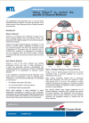 |
AN-BYRES119 - Using Tofino to control the spread of Stuxnet MalwareThis application note describes how to use the Tofino Industrial Security Solution to prevent the spread of the Stuxnet worm in both Siemens and non-Siemens environments. Keywords: Tofino, Stuxnet, Network Security
|
 |
TAN1001 - Lightning surge protection for electronic equipment - a practical guideThis publication discusses the nature of the threat to electronic instrumentation and communications networks posed by voltage surges induced by lightning or other causes. The practical application of surge protection devices (SPDs) designed to prevent damage from such sources is described. Keywords: Surge protection, lightning, electronic equipment
|
 |
TAN1002 - Lightning & surge protection - basic principlesThis publication discusses the nature of the threat to electronic instrumentation and communications networks posed by voltage surges induced by lightning or other causes. The practical application of surge protection devices (SPDs) designed to prevent damage from such sources is described. Keywords: Surge protection, lightning, electronic equipment, communications, networks, SPD
|
 |
TAN1003 - Earthing guide for surge protectionThis publication discusses the major aspects of earthing surge protection devices (SPDs). The relationship between SPD earths and the earthing of associated instrumentation or other equipment with which the devices are used is also considered. >Keywords: Surge protection, lightning, electronic equipment, earthing, grounding, SPD
|
 |
TAN1004 - Surge protection for intrinsically safe systemsThis publication discusses the nature of the threat to intrinsically safe instrumentation in hazardous areas from voltage surges induced by lightning or other causes. The practical application of surge protection devices (SPDs) is also considered taking into account the certification/approvals requirements. Keywords: Surge protection, lightning, electronic equipment, SPD, IS, intrinsic safety
|
 |
TAN1005 - Surge protection for Zone 0 locationsThis note discusses the surge protection requirements of intrinsically safe circuits entering a Zone 0 hazardous area. It analyses the potential gradients generated by lightning strikes and their possible routes of invasion. The alleviation of the problem at the Zone 0 interface transfers the problem elsewhere and an adequately safe pragmatic solution is proposed. Keywords: Surge protection, lightning, electronic equipment, SPD, IS, intrinsic safety, Zone 0
|
 |
TAN1006 - Surge protection for weighing systems - an application guideThis publication discusses the nature of modern weighing systems and describes the various methods by which surge protection can be applied to load cells (digital and conventional), to control systems, etc, within the weigh cabin and to external system links. Keywords: Surge protection, lightning, electronic equipment, weighing systems, load cells
|
 |
TAN1007 - Surge protection for Local Area NetworksThis publication discusses ways in which Local Area Networks can be damaged by lightning-induced transients, and how they can be protected economically. Keywords: Surge protection, lightning, electronic equipment, LAN, networks
|
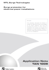 |
TAN1009 - Surge protection for electrical power installationsThis publication discusses the affects of surges and lightning induced overvoltages on ac power systems. The note will introduce the source of many common transients and surges and suggest the application of surge protection devices in this area. Finally, typical examples are shown for common installations. Keywords: Surge protection, lightning, power systems, transients
|
 |
TAN1010 - Lightning & surge protection for fieldbus systemsThis publication discusses the major aspects of a fieldbus system including the background history, highway components, I.S. applications and surge protection required to ensure that the Fieldbus system is protected against any destructive effects caused by lightning. Keywords: Surge protection, lightning, fieldbus
|
Download Product Certificates
Worldwide Product Range
ELPRO products are available in both Spread Spectrum 900MHz and Fixed Frequency 220/450/869MHz
|
Country |
Spread Spectrum |
Fixed Frequency |
|
USA/Canada |
License-free, up to 4W ERP |
450 MHz band licensed, to 5W |
|
Mexico & |
License-free, up to 1W ERP |
400 MHz band licensed, to 5W |
|
Europe |
|
869 MHz license-free 500mW |
|
Australia & |
License-free, up to 1W ERP |
472 MHz license-free, 100mW |
|
China |
|
220 – 235 MHz, licensed, 5W |
|
Japan |
|
426 MHz license-free 10mW |
|
Asia |
License-free in some countries |
370 – 520 MHz licensed channels, to 5W |
|
Middle East |
License-free in some countries |
370 – 520 MHz licensed channels, to 5W |
|
South Africa |
|
433 MHz license-free, 100mW |
|
Africa |
License-free in some countries |
370 – 520 MHz licensed channels, to 5W |
Eaton is committed to a policy of continuous improvement for all of its manufactured products. The information contained on these legacy product pages is meant to provide reference data for discontinued items from the MTL product line only.
For more information on migrating or equivalent product options <click here>
We are currently re-designing our website and support functions and as part of the re-development ........
To access the existing MTL downloads system please click here
|
The MTL7700 range, with their advanced features, should be regarded as your first choice for all new designs or installations. The recommendations below are based therefore on the MTL7700 range. Users of MTL700, 4700 or 7000 range can also use the guide because of our consistent numbering policy. Products, in any barrier range, that have the same two last digits (ignoring letters and ‘+’ symbols) will have very similar characteristics, e.g. MTL7787 and MTL787. |
|||||||||||||||||||||||||||||||||||||||||||||||||||||||||||||||||||||||||||||||||||||||||||||||||||||||||||||||||||||||||||||||||||||||||||||||||||||||||||||||||||||||||||||||||||||||||||||||||||||||||||||||||||||||||||||||||||||||||||||||||||||||||||||||||||||||||||||||||||||||||||||||||||||||||||||||||||||||||||||||||||||||||||||||||||||||||||||||||||||||||||||||||||||||||||||||||||||||||||||||||||||||||||||||||||||||||
|
|||||||||||||||||||||||||||||||||||||||||||||||||||||||||||||||||||||||||||||||||||||||||||||||||||||||||||||||||||||||||||||||||||||||||||||||||||||||||||||||||||||||||||||||||||||||||||||||||||||||||||||||||||||||||||||||||||||||||||||||||||||||||||||||||||||||||||||||||||||||||||||||||||||||||||||||||||||||||||||||||||||||||||||||||||||||||||||||||||||||||||||||||||||||||||||||||||||||||||||||||||||||||||||||||||||||||
| The following guide is for users who require guidance on their choice of isolator for a new installation. For a given application the choice is between DIN-rail mounting (MTL5000/MTL5500 range) and backplane mounting (MTL4000/MTL4500 range) devices. If additional guidance is required, contact your local representative.
| ||||||||||||||||||||||||||||||||||||||||||||||||||||||||||||||||||||||||||||||||||||||||||||||||||||
| ||||||||||||||||||||||||||||||||||||||||||||||||||||||||||||||||||||||||||||||||||||||||||||||||||||
| ||||||||||||||||||||||||||||||||||||||||||||||||||||||||||||||||||||||||||||||||||||||||||||||||||||
| ||||||||||||||||||||||||||||||||||||||||||||||||||||||||||||||||||||||||||||||||||||||||||||||||||||
| ||||||||||||||||||||||||||||||||||||||||||||||||||||||||||||||||||||||||||||||||||||||||||||||||||||
| ||||||||||||||||||||||||||||||||||||||||||||||||||||||||||||||||||||||||||||||||||||||||||||||||||||
| ||||||||||||||||||||||||||||||||||||||||||||||||||||||||||||||||||||||||||||||||||||||||||||||||||||
| ||||||||||||||||||||||||||||||||||||||||||||||||||||||||||||||||||||||||||||||||||||||||||||||||||||
| ||||||||||||||||||||||||||||||||||||||||||||||||||||||||||||||||||||||||||||||||||||||||||||||||||||
| ||||||||||||||||||||||||||||||||||||||||||||||||||||||||||||||||||||||||||||||||||||||||||||||||||||
| ||||||||||||||||||||||||||||||||||||||||||||||||||||||||||||||||||||||||||||||||||||||||||||||||||||
| ||||||||||||||||||||||||||||||||||||||||||||||||||||||||||||||||||||||||||||||||||||||||||||||||||||
| ||||||||||||||||||||||||||||||||||||||||||||||||||||||||||||||||||||||||||||||||||||||||||||||||||||
| ||||||||||||||||||||||||||||||||||||||||||||||||||||||||||||||||||||||||||||||||||||||||||||||||||||
| ||||||||||||||||||||||||||||||||||||||||||||||||||||||||||||||||||||||||||||||||||||||||||||||||||||
When it comes to HART Multiplexers, MTL offers the most cost effective, reliable and flexible solutions for every application and industry. From Siberian oil fields to Mexican power plants, MTL HART Multiplexers provide the optimum solution.
A typical small 16-channel system is illustrated below.

HART Multiplexers copy the HART digital signal from the 4-20mA signal, which then passes to the control/safety system unscathed, and sends the HART data directly to the maintenance software control stations. Multiplexers offer an extremely flexible and reliable system which can handle anything from a handful to thousands of HART devices on one network.
Designed for Antennas (RF), Weighing Systmes, Load cells and a comprehensive line of Security Cameras.
Modular communication line protection designed for multi-port or single port applications.
Covering all applications for both private wire and public switch telehpone networks.
Safeguarding the integrity of the entire fieldbus system including AC power, transmitter and/or trunk protection.
We design and manufacture a wide range of protection solutions for all of your system surge protection requirements. We offer a wealth of over 50 years experience in the surge protection industry. Our surge products embodies the strengths of Telematic, a name synonymous with the water industry, and Atlantic Scientific, which has strong ties in the network, ITS and wireless infrastructure markets.
We continue to develop and support these markets with leading designs and solutions, as well as continuing to be a leader in surge protection in the process industry.
Our commitment is not only to meet but surpass our customer’s high expectations which can only be achieved by maintaining very high standards in all aspects of our business. We continue to listen to our customer needs and develop solutions which not only meet, but exceed requirements in all respects.
To download a copy of the MTL Surge brochure click here
For more information about MTL Functional Safety Management click here.
High quality AC and DC surge protection for commercial and industrial facilities.
Designed as a Panel PC, the new EXPLORER is also based on a modular concept - in line with our world-wide established CHALLENGER remote PC terminals.
Whether for local display or operation of software in Ex Zone 1 / 2 / 21 / 22; for client server applications, such as a web terminal; or for control of PLC, balances etc - the EXPLORER Panel PC offers maximum adjustability to individual requirements.
High quality construction, ease of installation and a range of module options, makes CHALLENGER PC terminals the optimum solution for on-site operation. As a Remote Station they only require the connection to the VGA / mouse / keyboard of a process computer, and the CHALLENGER transmission unit transfers the data up to 600m locally – with brilliant image quality. The PC stays in the clean area, and so allows hardware and software changes without any problems. Choose between our terminals here on the basis of the DATA TRANSMISSION DISTANCE.
This is the Temporary Yokogawa page
Please note that the 9200 range of Ethernet switches has been terminated.
| Product Termination Notice | ||
| Statement issued | Last Time Buy | Replacements and notes |
| 17 August 2017 | 22 December 2017 |
*No direct replacement |
*We will be offering a new full range of ruggedised ethernet products all designed to operate in a harsh process control environment in the future.