FAQs in Intrinsic Safety & Process I/O
Questions
- MTL55xx isolator datasheet stats that it could be used in SIL3 rated safety function loops so can th
- MTL show the Safety Description of the zener barriers on the data sheet, but it only shows voltage,
- I am applying 24Vdc to an MTL7787+ to drive a 24V relay coil but it doesn’t work. Why not?
- I cannot get an output from the SAFE side of a MTL5032. What is the problem?
- Can I use MTL5000 series for safe area applications ?
- What distance can you cover between two MTL5051s in separate hazardous areas?
- MTL5000 Series - What crimp ferrules are available for 1.5mm2 wire ?
- MTL5042; what is the safety description for terminals 1 and 3?
- What is the difference between the MTL4045B and MTL4045C?
- MTL4073 - What is the hazardous input resistance and safe area output impedance ?
- What causes the I/P, MTL4045B, DCS output card to ‘lock-up’?
- What is the response time of the MTL3073, 4073, 5073, 5074 temperature converter?
- MTL4041B - What is the input resistance at hazardous area pins 5 and 6?
- What is an “IS earth”?
- How do the “simple apparatus” rules relate to the current “well defined” parameters?
Answers
MTL55xx isolator datasheet stats that it could be used in SIL3 rated safety function loops so can th
Look at the definitions of the safety integrity levels. If a component has been assessed as suitable for use up to SIL3 then it can also be used in loops that need to achieve SIL2 or SIL1.
MTL show the Safety Description of the zener barriers on the data sheet, but it only shows voltage,
Yes, you have to ensure that the barrier power value is not greater than the power value given for the field equipment.
The maximum power transfer between the safe area and the field takes place when the impedance of the source is equal to the impedance of the load. This is called the Matched Power.
This is the worst case condition and so this is used to calculate the power output from a barrier. Under these conditions the power can be expressed as:-
Matched Power = Voc x Isc / 4 (W)
For a typical 24V dc barrier, MTL7728+, with safety description 28v, 93mA.
28 x 0.093 = 2.604
2.604 / 4 = 0.651W
However the power value for each channel of a barrier is provided in the Maximum Cable Parameters table for each barrier series.
I am applying 24Vdc to an MTL7787+ to drive a 24V relay coil but it doesn’t work. Why not?
You are not taking into account the resistance of the barrier.
For optimum efficiency, the resistance of the relay coil should be the same as the resistance of the barrier (i.e. “matched”). However, this means that you will get only half the supply voltage (12V) at the relay coil.
You should therefore use, for example, a 12V, 400 ohm relay coil.
Rt (Total resistance) = Rb (Resistance of barrier) + Rc (Resistance of coil)
Isupply (Current flowing in circuit) = Vsupply / Rt
Vc (Voltage at coil) = Rc x Isupply.
Alternatively you could use an MTL774X product which provides simple “volt-free” contacts in the safe area to operate the relay coil.
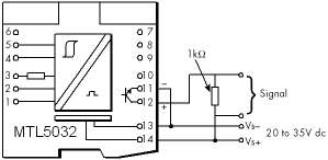
I cannot get an output from the SAFE side of a MTL5032. What is the problem?
|
The output terminals 11 and 12 are not powered so you will have to provide the voltage. Below is a typical circuit showing a 24 VDC supply.
|
Can I use MTL5000 series for safe area applications ?
When using MTL5000 series modules in safe area applications, it is important to change the “blue” connectors for appropriate “grey” connectors, labelled correctly for safe area use. For such applications, two new safe area connectors are now available, as detailed below.
Part no.
SAF1-3 available as standard accessory
SAF4-6 available as standard accessory
What distance can you cover between two MTL5051s in separate hazardous areas?
MTL5051 remote signalling baudrate formula - Back-to-back mode across hazardous area.
Max baudrate = 0.25 / (R x C x L2) or Max. distance = Sq Root ( 0.25 / (R x C x B)) where:
R = cable resistance [ohms/m]
C = cable capacitance [Farads/m]
L = length [m]
B = baudrate [baud]
So for example, with a 2Km cable of 100pF/m and 40mohm/m:
Max baudrate = 0.25/(40x10-3.100x10-12.(2000)2) =15,625baud
[Note that this assumes that the cable has 2 cores plus a screen, with the screen used for the Common connection].
MTL5000 Series - What crimp ferrules are available for 1.5mm2 wire ?
We have not been able to locate any ferrules with 12mm length metal tubes for 1.5mm2 wire in any supplier catalogues (unless you have seen any?!).
We recommend you use the following 18mm metal tube length ferrules:-
PKE1518 (1.5mm2) and PKE2518 (2.5mm2) from Cembre, and cut them to 12mm length after crimping.
MTL5042; what is the safety description for terminals 1 and 3?
Non-energy storing apparatus can be connected between terminals 1 and 3.
See under ‘Safety description, Terminals 1 to 3’ in the MTL5042 data specification.
Terminals 1 and 3 can be connected into an IS loop as long as the open circuit voltage <28 V. Therefore, determine the output safety parameters for the field device and ensure they comply with this voltage.There are no specific cable parameter figures provided for this combination of terminals on that certificate. The only reference to cable parameters on the certificate is on page 3:-
“The capacitance and either the inductance or the inductance to resistance ratio (L/R) of the load connected to the output terminals must not exceed the following values: Group IIC - Co < 0.13uF, Io < 4.2mH or L/R < 55uH/ohm"
What is the difference between the MTL4045B and MTL4045C?
MTL4073 - What is the hazardous input resistance and safe area output impedance ?
10V/m with 1kHz sine wave modulation to 80% of the carrier level are the minimum RF levels specified in the Generic Immunity Standard for Industrial Environments EN50082 part 2.
What causes the I/P, MTL4045B, DCS output card to ‘lock-up’?
This very rare loop lock-up problem with MTL4045Bs is associated with higher inductance I/P devices (of which there are not many). The short-circuit detect in the MTL4045B triggers a series of events in the I/P, MTL4045B, AO card loop which locks it up. The remedies are either:
- Insert a resistor (as high a value as possible
- Change to the MTL4045C
It is not a simple matter to characterise the specific properties of the I/P devices that cause this problem with the MTL4045B, because it depends on the combination of the inductance and damping properties of the device.
When testing, try the resistor solution first, but otherwise, if possible, change to the MTL4045C.
What is the response time of the MTL3073, 4073, 5073, 5074 temperature converter?
These units convert data every 400ms, i.e. about 2.5 times per second.
The data is pipelined to the output, i.e. the previous sample is output during the time that the current input sample is measured. Hence the maximum delay between a change of input and the output settling may be 800ms. If smoothing and/or damping is selected, then the output will settle to the new value more slowly, but the output update is always 2.5 per second.
MTL4041B - What is the input resistance at hazardous area pins 5 and 6?
Less than 50 ohms, and typically 30 ohms.
What is an “IS earth”?
Protective earthing is a vital part of the safety of almost all electrical systems where potentially explosive gases may constitute a hazard. Correct earthing is important for all protection techniques, including intrinsic safety.
Adequate earthing, though not spelled out in the particular installation codes, is absolutely vital to the safety of all mains-powered electrical equipment, whatever the protection technique. Section 22 of the BS 5345 Part 1 lists no special requirements for the earthing of hazardous area systems but is a convenient cross reference to other documents.
BS 5958: Part 1: 1980, which is a code of practice on the avoidance of static hazards and contains some sound practical advice, should be read as good background information on which to build.
Consider a conventional site with a local distribution transformer and with the neutral star point connected to the standard earth mat. The primary purpose of this mat is to provide an earth return path for any faults that may develop in the distribution system, where the conductivity of the soil may provide a possible current path. Conventionally, each electrical installation provides a return path to the neutral star point in its wiring, via either the cable armour or a specific conductor which is capable of operating its protective network. This is supported by the interconnection of the equipment to the metallic structure which generates a web of structural interconnections to the various electrical equipment return paths. Further support is usually provided by the structure and the antistatic bonds which are normally present. There is nearly always a third parallel path through the soil, but this indeterminate path is not usually relied upon for first line safety connections.
The more probable source of direct invasion of intrinsically safe circiuts is within the safe area shown in Fig. 9.2. The first essential of the dafety earth on the barrier busbar is to provide a return path of low impedance so as to prevent any significant proportion of the faule current entering the hazardous area. This fault current is returned to the neutral star point bond and hence back to the distribution transformer.
The current flowing though the bonding conductor generates a potential difference between the IS earth point at the barriers and the neutral star point. The outside of the field-mounted instrument is bonded to the neutral star point, and the internal circiuts of the instrument are connected to the barrier busbar. The potential difference between IS earth point at the barriers and the neutral star point is therefore transferred to the hazardous area. It is normally safe because this internal circuits are isolated from the instrument housing, but this potential difference should be minimised so that if there is a local insulation failure no danger can arise. The installation conditions of barriers, screened transformers etc. nearly all call for a return path impedance less than 1 ohm. A figure of 0.1 ohm is normally achievable and is more desirable. It is important to remember that the resistance involved is that of the return conductor between points IS earth at the barriers and the neutral star point and the resistance of the earth mat is not important for this purpose. These principals are normally applied within the UK.
How do the “simple apparatus” rules relate to the current “well defined” parameters?
The relevant clause in the standard IEC 60079-11 is 5.4, and states in section b) “sources of stored energy with well defined parameters, for example capacitors or inductors, whose values shall be considered when determining the overall safety of the system”.
This was introduced because the 20 microjoule figure of the previous definition is difficult to defend. Adding 20 microjoules to a IIC system, which may already be on the acceptable limit more than removes the safety factor. Another problem is that a thermocouple delivering 10 mV and 1 mA generates 20 microjoules in 2 seconds, hence the energy figure should have had a time assosciated with it.
The new clause does allow a further degree of freedom, particularly if IIB and IIA gases are being considered. The analysis should assume that all the capacitors and inductors within an apparatus are added together and considered as appearing directly across the terminals of the apparatus.The draft system standard requires that the sum of ALL the relevant parameters of ALL simple apparatus within an IS circuit shall be taken into account. Implicit in the same document is that a justification of why a piece of apparatus is considered as “simple” should be included in the safety documentation. The redrafted clause does give greater flexibility,but is not significantly different from considering the capacitance and inductance of cables.
The clause does allow the construction of some complex circuits, but whoever makes the claim of “simple apparatus” must document the analysis, sign it, and accept responsibility for it. It is a usefull solution to the occasional difficult short term problem. However, if a product is to be sold in significant numbers it will almost certainly have to be certified. Care should be taken when analysing simple apparatus to apply the full clause including the restrictions of the second part. This means that any complex apparatus can only be analysed by someone who is familiar with the whole standard and is knowledgeable in the field of intrinsic safety. Such persons are VERY RARE!