Even though all data lines stay within the building, communication interfaces are still susceptible to damage. There are two reasons for this. 1. Induced voltages from a nearby lightning strike when control/communications lines run near electrical power wires, metal in the building structure, or near lightning rod ground leads. 2. Differences in AC power voltage references between two devices connected together by control/communication lines. When an event, such as a nearby lightning strike, migrates in on the AC power, individual equipment within the building can see large voltage reference differences. When these devices are connected together by low voltage control/communication lines, the control/communication lines try to equalize the difference, thus causing damage to the interface chips.
Frequently Asked Questions
Contains the answers to the questions we’re most often asked. Use the selection below to narrow you search.
-
All my data lines run inside the building, why do I need to protect them?
-
All standard MTL surge products have a 10 year warranty. What does MTL mean when they say this is a 10 year “no fuss” warranty?
Simply stated the 10 year “no fuss” warranty means that if the product fails within the 10 year period it will be replaced. This warranty includes damage for lightning or from utility power faults. This means that you can be assured that you will not have to purchase another suppressor for this application for at least 10 years. This warranty goes well beyond most other competitors who only warrant their products from failures due to their materials or workmanship. Most do not cover failures due to lightning or utility power faults.
- Answers to Frequently asked questions on Azonix could be found below
- Answers to Frequently asked questions on Gas Analysers could be found below:
-
What would the appropriate measures be to protect the devices attached to MTL managed switches (eg PLC’s or HMI’s) from hackers or viruses?
The fitting of a hardware firewall (such as Tofino) upstream & adjacent to the switch will stop the switch from being vulnerable to attack. A further level of protection could be achieved by fitting hardware firewalls between the switch & the end devices connected to it.
-
Are MTL backplanes SIL certified?
No, once again these are regarded as ‘wiring components’ in a similar manner to terminal blocks.
-
Are MTL barriers SIL certified?
In the context of ‘functional safety’, simple shunt-diode zener barriers do not perform a safety function and are regarded as just ‘wiring components’. Thus the reliability in terms of the MTBF figures is all that is taken into consideration for the safety loop. The more complex or ‘active’ zener barriers, such as the MTL7706+ or the MTL774x models, will be considered for their use in functional safety applications at a later date.
-
Are MTL switches mounting orientation sensitive?
Generally mounting is preferred “upright”, but the devices will still function if eg rotated 180 degrees. Remember they are fanless units, so heat convection is less of an issue than with non industrialised products.
-
Are the Annunciators suitable for use in harsh environments?
RTK/ MTL annunciators are provided with optical isolation for all of the control inputs as standard. (signal & pushbutton inputs). They are are fully EMC compliant. A high percentage of our annunciators have been in service for many years in harsh environments including offshore platforms, petrochemical plants, nuclear plants, power stations and sub-stations.
-
Aren’t Wireless LANs insecure?
Saying a wireless LAN is insecure is like complaining a car, with central locking, an immobiliser and alarm is insecure when it is unlocked. All Wireless Access points support some degree of security, most people do not turn this security on, and as such Wireless technology was perceived as being insecure.
Some of the common security steps include: -
Physical Security: By using appropriate antennas it is possible to restrict the propagation of the radio waves as needed. So if a link is to be based in a building, using a patch antenna attached to the wall will severely restrict the amount of radio waves that propagate through that wall and so the ability to pick up this information. Failure to address physical security could be likened to hanging a network cable out of a window.
MAC Layer security: The 802.11 standard specifies two main technologies to secure the MAC layer of the wireless network.
WEP: Wired Equivalent Privacy uses keys to encrypt the data that is being transmitted, without the appropriate key the data is unreadable to anyone receiving the data. WEP is a “crackable” standard, this means that using appropriate software, and a few days of monitoring the wireless network it is possible to gain the key and therefore decrypt the data.
WPA: WiFi Protected Access has been introduced by the WiFi alliance in order to provide increased security until the 802.11 standard ratifies a more secure method than WEP, it once again uses keys to encrypt the data being transmitted, but in this case the keys are constantly changed to prevent them from being recovered using software. WPA is currently regarded as “uncrackable”.
VPN: Virtual Private Networks are a technology that is used to allow secure communications across public networks (primarily the Internet). These same technologies can also be used to secure data being transmitted across wireless mediums. Once again these devices encrypt data so that without the correct keys the data is unreadable, there are various technologies used including DES, 3DES and AES. The American Military regard 3DES (pronounced triple DES) as secure.
Using a combination of these technologies it is possible to restrict how can pick up your signal, when they have intercepted it they have to decrypt the MAC layer, and once this has been completed they have to decrypt the VPN layer, this level of security far exceeds the security used on cabled systems and makes other means of gathering the information (such as staff corruption) much more attractive and likely.
-
As MTL are a certified FSM company can they provide guidance in developing a SIL loop?
No, the design of the safety function is the responsibility of the user not the vendor. MTL provide the information needed to select, install, operate and maintain our products in the Safety Manual.
-
Can a Gigabit switch be connected to a Fast Ethernet switch?
Yes however the system will auto-negotiate to the speed of the slowest device.
-
Can a manufacturer such as MTL state their products are “SIL 3 certified” rather than “suitable for use in a SIL 2 system”?
The steps required to define, design, verify, install and commission safety functions are given in the life cycle contained within the standards. For the process industries the IEC 61511 standard is the sector specific standard to follow and it would be foolish to attempt any activity for a safety function without reference to this standard.
-
Can a MTL unmanaged switch connect to a Hirschmann (or another manufacturers) unmanaged
switch?
Yes - typically with a Cat 5 100Mbps copper ethernet cable or a fibre optic cable, eg when being used to provide extra localised connection ports.
-
Can a switch be connected to a Wireless ethernet router or access point?
Yes - typically by using a Cat 5 copper ethernet cable at 100Mbps full duplex (FDX)
-
Can a switch function as a router?
In some instances a managed ethernet switch can be set to function as the “default gateway” or router for a network.
-
Can an individual product (i.e. Isolator) be SIL rated?
Products (components) must be suitable for use in a safety loop (function) up to the integrity level that the loop is to achieve. Remember that it is the complete safety loop or safety function that has a Safety Integrity Level and not a particular component. Each component, by itself, does not perform a safety function – it is the complete chain of components operating together that implement the safety function designed to mitigate the identified risk.
-
Can an unmanaged switch be used as part of a Redundant Ring architecture?
This is not recommended as the full performance of a managed network could not be achieved
with this mixture of managed & unmanaged devices. -
Can diagnostic data from a switch on an ethernet Local Area Network (LAN) be exported & visualised into eg a SCADA package?
Yes - Using SNMP software running on the network to diagnose & monitor the LAN, combined with OPC server software which will enable export of data to & from the SCADA application.
-
Can I create backups for my Tofino configuration?
The Tofino locks its config files to a specific device ID (MAC address). The MAC address is part of the config file name. This means you can have multiple config files on a single ACA. However, you can’t create a config file that can be loaded into any device - you must enter the device’s specific MAC address into the CMP software before generating the config files.
So the best way to handle replacing a failed device is to keep one spare hardware device on hand, keep one spare set of licenses in the Tofino CMP software, and keep the Tofino CMP software accessible. Here is the procedure to configure the replacement device when one of the in-service devices fails:1. Physically swap the failed device with the replacement. MAKE NOTE of the ID number (MAC address) of the new device.
2. In the Tofino CMP software, locate the icon in the Network Editor that represents the failed device. Edit the ID number for this icon, replacing it with the ID number of the new replacement device, and click OK to save the changes.
3. If Tofino CMP has a network connection to the replacement Tofino, you can download the configuration to the replacement device by right-clicking on the icon in the network editor and selecting “Sync Tofino”. Otherwise, you can right-click on the icon and select “Create loadable USB key” to save the config files to an ACA, then carry that ACA to the replacement device and load the config into it. -
Can I move my CMP (central management platform) to another PC? If so, how?
CMP may be moved to another PC using the following steps:
1. Log in to CMP and create a backup of your existing configuration database (“Tools | Database Admin | Database Backup…” menu item)
2. Install CMP on the new PC. If installing on Windows Vista, Windows 7 or Server 2008 then please take note of the special requirements in Appendix B of the CMP installation guide.
3. License CMP on the new PC using the same License Activation Key that was used on the existing CMP computer.
4. Once CMP is licensed on the new computer, transfer the backup file that you created in step 1 above and restore it into the new CMP using the “Tools > Database Admin > Database Restore…” menu item. -
Can I replace a SIL2 rated isolator from one supplier with another supplier product with the same SIL rating and safety parameters?
Essentially yes, but once you have satisfied that the operational parameters, the intrinsic safety parameters and the functional safety parameters are compatible, then updated the loop design records and documents to support the change. This must then be verified by the safety system designer with the appropriate level of competence. Remember also to consider the proof-test requirements for the new component compared to the old one to ensure the PFD is not impaired. In similar vein to the requirements for maintaining intrinsic safety loops, then any change likely to affect the functional safety of a loop must be adequately assessed, documented and approved.
-
Can I use a field device that is not FISCO certified with the MTL FISCO power supplies?
Yes. Field devices that are only certified to the entity profile can be used with the MTL FISCO power supplies by including a spur connector in the connection to that device. The entity spur connector is usually located in the fieldbus junction box.
-
Can I use MTL5000 series for safe area applications ?
When using MTL5000 series modules in safe area applications, it is important to change the “blue” connectors for appropriate “grey” connectors, labelled correctly for safe area use. For such applications, two new safe area connectors are now available, as detailed below.
Part no.
SAF1-3 available as standard accessory
SAF4-6 available as standard accessory -
Can I use Redundant Ring with another brand of ring switch, or another ring protocol?
No, Redundant Ring may only be used to connect to other MTL Redundant Ring-capable devices.
-
Can I use VLAN with Tofinos?
Tofino is completely transparent to VLAN tagged traffic. If the traffic is tagged, and it is allowed by the user’s firewall rules to pass through the Tofino, then the VLAN tag will be preserved on the traffic. This means that the Tofino can be installed on VLAN trunks if desired. The firewall rules created by the user do not filter based on VLAN tags, they can filter only on IP address and protocol. This usually does not create any problem when VLANs are used however, in most installations each VLAN tag is associated with a unique subnet.
-
Can managed and unmanaged switches could be connected together?
Yes, but for best system optimisation & diagnostics, the utilisation of managed switches throughout
is advised. -
Can MTL switches connect to office grade switches from e.g. HP or Cisco?
Yes they are all ethernet switches and so can communicate with each other, either as unmanaged
or managed devices. -
Can Redundant Ring and RSTP be enabled on the same switch?
Yes, however, a particular port may only be used for one protocol or the other. For example, if a port is part of a Redundant Ring, that port cannot also participate in a spanning tree.
-
Can switches be connected to Routers?
Yes - typically using a 100Mbps or 1Gbps Cat5/6 copper cable or fibre optic cable for longer distances.
-
Can switches be connected using either copper or fibre optic cable?
Yes using either the built-in fibre connectivity of the switch or by using a converter.
-
Can switches be protected from unauthorised user access?
Yes. By using password protection either at the network management software level or at port level on the switch itself by switching the port “off”, or by password authentication in the switch.
-
Can the CMP software / Tofino routing through another server?
Yes, CMP and Tofino need ports 6689 or 65000 open to communicate through a Firewall
-
Can the copper port or fibre optic connections on a switch be disabled if required?
Yes, by setting a port to disabled using the configuration software.
-
Can the existing 932x-SC Spur Connectors be used to connect to 'Entity' certfied fieldbus devices, and devices in Zone 0 hazardous areas?
Yes, these can be used on Redundant FISCO segment in exactly the same way as for simplex.
-
Can the modules be 'hot-swapped' to allow replacement of failed modules without losing power or communications?
Yes. The power supply and Supply Arbitration Modules may be easily ‘hot swapped’ without powering down the system, and without causing loss of power or communications.
-
Can you deploy Tofinos in a redundant network?
YES - Generally Tofino can be used on redundant networks based on systems like Spanning Tree Protocol (STP), Fault Tolerant Ethernet (FTE) and others straight out of the box.
-
Could a MTL unmanaged switch connect to a Hirschmann (or other manufacturers) MANAGED
switch?
Yes - typically with a Cat 5 100Mbps copper ethernet cable or a fibre optic cable, eg when being
used to provide extra localised connection ports. -
Could MTL and Cisco switches reside on the same subnet?
Yes.
-
Do I need to use a special “cross over” cable to allow communication between a switch and for example a PC?
No – most industrial ethernet switches now have “auto crossover” as a built in feature.
-
Do I need to use any specific type of USB drive for the Tofino?
Tofino requires USB storage devices that are compatible with revision 2.0 of the USB specification. The device need NOT be a high-speed device, full-speed devices also work. The following brands are listed in the Tofino CMP manual as being compatible:
• Kingston Data Traveler
• SanDisk cruzer
• Sony Microvault
• LexarIn addition, we have regularly used the 2 GB and 4GB Verbatim USB memory sticks successfully.
-
Does an unmanaged switch require any setting up to enable it to transmit to other devices?
Unmanaged switches are generally “plug & play” devices.
-
Does removing or repowering a MTL4841 affect the analogue signals?
The MTL4841 and MTL4842 can both be removed or the MTL4841 re-powered without interfering with the analogue 4-20mA signal.
-
Does the Redundant FISCO power supply work with existing Intrinsically Safe Megablock wiring hubs, or do they need to be different?
Redundant FISCO works with MTL’s existing range of IS Megablocks (types F245 – F271).
-
Doesn't the FISCO standard say that there should only be one source of power in a FISCO network, making it impossible to have redundant power supplies?
No. This clause in the IEC60079-27 standard is intended to mean that the maximum values of Uo, Io and Po for the power supply must not be exceeded on any segment, and that the power must be connected at only one point on the bus. MTL’s solution complies with both these requirements because it provides power onto the segment at only one point (at the power supply terminals), and the Uo, Io and Po values for the redundant output will be certified to comply with the maximum values specified for FISCO.
-
Even if the incoming phone lines are protected do I need additional protect the telephone lines?
The protection the Phone Company provides is there mainly for personal safety to prevent lightning from migrating in on their wires and causing personal injury. It provides little protection for sensitive electronic communications equipment. It provides primary protection but does not eliminate the need for secondary protection at the equipment.
-
How can I access MTL Partner portal?
MTL offers its key customers and partners access to its customer portal. Customer portal could be accessed via the MTL Extranet. This requires registration and the registration process could take up to 3 working days.
-
How can I evaluate the firewalls rules that I've created?
The first firewall rule that matches a packet will determine what the firewall does with that packet, based on the ‘permission’ setting of the rule. If no rule matches a packet, then the default action is to block that packet and generate an alarm.
When using Tofino CMP, firewall rules are evaluated in the following order:
1. Rules for non-IP protocols in the firewall tab of each Tofino icon
2. Rules for IP-based protocols in the firewall tab of each Tofino icon
3. Rules for IP-based protocols on the firewall tab of each protected device under a Tofino (‘Talker’ rules)
All rules are evaluated top to bottom as displayed visually in the CMP network editor, within the groups outlined above. Where multiple rules match the same packet, the first rule that is evaluated will determine how the packet is processed. For example, if a Tofino has a global rule that allows Modbus/TCP traffic, and there is also a Talker rule on a protected device under the same Tofino that uses the Modbus TCP Enforcer to perform content inspection on
Modbus/TCP traffic, the Modbus/TCP traffic will be allowed without inspection since the global rule is evaluated before the talker rule.
Rules can be re-ordered by the user on any firewall tab, except that Global rules will always be evaluated before Talker rules (top to bottom, as described above). CMP always displays them in alphabetic order based on the device name, but devices in the network editor can be re-ordered by changing the device name to get the desired rule evaluation order. -
How could a PLC using MODBUS/TCP possibly be a security risk to my control system?
MODBUS has no authentication and may be easily spoofed so any MODBUS devices controlled/monitored by Windows PCs which may be compromised.
-
How do I get started with a Tofino security appliances?
Here are a couple of resources that may be helpful in getting started with Tofino:
1. The first section of the CMP user guide is entitled “15 steps to a secure control system.” This is a great step-by-step introduction to setting up a Tofino, modelling your control network, configuring some firewall rules and then testing the rules before deployment. Please note that the Tofino is an Ethernet bridge (like an Ethernet switch) with no IP address, so to discover the Tofino as described in the tutorial, you must connect it between your CMP computer and another device that DOES have an IP address. Additionally, when you perform the “Tofino Discovery” as described in the tutorial, the IP address that you should scan is the IP address of the device BEHIND the Tofino (opposite side of the Tofino from your CMP computer).
2. We have a demonstration video on our website that provides a basic introduction to Tofino, and give examples of configuring the key security modules.This video is accessible using the link below:
http://www.mtl-inst.com/training-education/demonstration-videos/mtl_industrial_security_solution_live_demonstration -
How do I initiate an RMA ( Return Material Authorisation) or Product Return?
For MTL Intrinsic Safety, Fieldbus, Industrial Ethernet and Industrial Wireless Products please contact your local MTL sales office or representative.
For Gecma / HMI products please indicate and RMA via RMA Portal.
-
How do I preform a factory reset on an MTL9211-ET Tofino hardware unit?
Power the Tofino off, hold down the large mode button while you power it up, keep holding until all four LEDs blink twice. It may take as long as 2 minutes. Once they blink you can release the button and the Tofino has reset.
-
How do the “simple apparatus” rules relate to the current “well defined” parameters?
The relevant clause in the standard IEC 60079-11 is 5.4, and states in section b) “sources of stored energy with well defined parameters, for example capacitors or inductors, whose values shall be considered when determining the overall safety of the system”.
This was introduced because the 20 microjoule figure of the previous definition is difficult to defend. Adding 20 microjoules to a IIC system, which may already be on the acceptable limit more than removes the safety factor. Another problem is that a thermocouple delivering 10 mV and 1 mA generates 20 microjoules in 2 seconds, hence the energy figure should have had a time assosciated with it.
The new clause does allow a further degree of freedom, particularly if IIB and IIA gases are being considered. The analysis should assume that all the capacitors and inductors within an apparatus are added together and considered as appearing directly across the terminals of the apparatus.The draft system standard requires that the sum of ALL the relevant parameters of ALL simple apparatus within an IS circuit shall be taken into account. Implicit in the same document is that a justification of why a piece of apparatus is considered as “simple” should be included in the safety documentation. The redrafted clause does give greater flexibility,but is not significantly different from considering the capacitance and inductance of cables.
The clause does allow the construction of some complex circuits, but whoever makes the claim of “simple apparatus” must document the analysis, sign it, and accept responsibility for it. It is a usefull solution to the occasional difficult short term problem. However, if a product is to be sold in significant numbers it will almost certainly have to be certified. Care should be taken when analysing simple apparatus to apply the full clause including the restrictions of the second part. This means that any complex apparatus can only be analysed by someone who is familiar with the whole standard and is knowledgeable in the field of intrinsic safety. Such persons are VERY RARE! -
How do users assign IP addresses to managed MTLindustrial ethernet switches?
By using the web interface (plugging in to a copper port on the switch).
-
How does Tofino licensing work? Can I import a license grant file into CMP when a different CMP database is used?
When you license Tofino, there are 2 different types of license created - one for CMP, and the other for the Loadable Security Modules (LSMs) that you will use in the Tofino appliances. The CMP license is assigned to the PC that was used to create the license request file. If you try to import a CMP license grant file on a PC that is different from the PC used to create the license request file, it will fail with an error message. Every CMP database is assigned a unique ID number when it is created. The LSM licenses are tied to the CMP database that was is use when the license request file was created. If you try to import a license grant file into CMP when a different CMP database is used, it will fail with an error message. The error message you received is for the second case (database ID doesn’t match). This means that the CMP database changed between the time that the license request file was generated, and the time that the license grant file was imported into CMP. In this case, you should create a new license request file and e-mail it to .(JavaScript must be enabled to view this email address) We will generate a new license grant file which will work with your current CMP database. After you import that grant file, you can back up your CMP database (use the “Tools | Database Admin | Database Backup…” command in CMP) and your licenses will be saved in the backup file that is created.
-
How many rings can I configure using Redundant Ring?
You can configure up to four independent rings, as long as your device has enough ports to do so. For example, a five-port managed switch such as the 9205-ETM-2M/S switch can only support two rings, because it does not have enough ports to support four rings. However, the 10-port 9210-ETM-3G-2Fswitch does support the full four-ring limit.
-
How many switches can be supplied form one power supply?
This will depend on the output power (in Amps) of the power supply, but several switches could be powered from eg one 2.5A power supply if considered appropriate for the network installation.
-
How many switches can I connect in a Redundant Ring?
While there is no maximum, the larger the ring gets, the longer the network will take to recover from a failure. Our ring switches have been field tested with over 80 switches in a single ring.
-
How many switches can I connect in an RSTP network?
You can have a maximum of 40 hops in an RSTP network. Hops are the number of connections between the two farthest points on the network. In most practical networks, this means you cannot have more that 40 switches between any two points.
-
How quickly does the Redundant Ring protocol recover from a failure?
RTR can typically recover in 30 ms (milliseconds) plus 5ms per hop. For example, a four-switch ring would normally recover from a failure in 50 ms.
-
How to determine function codes and coil or register addresses for Modbus Enforcer rules?
It’s best if there is documentation available that describes what function codes and coil/register addresses are used, because it’s possible that some function codes or addresses may only be used intermittently or for certain operating modes of the plant. However, if documentation is not available then it’s also possible to determine the function codes and addresses by using Tofino’s test mode. The function codes can be determined by allowing just a single
function code that is known not to be used (for example, 127) and then run the Tofino in Test mode. The alarms will list all the function codes that are seen by the Enforcer.Once the function codes are known, then Modbus Enforcer rules can be set up for them but with a dummy register address range, for example 0-0. Alarm messages will be generated showing the register addresses that are actually being used, and then the address ranges in the rules can be adjusted to match. -
How to free the LSM licenses that are assigned to a missing Tofino?
The Tofino CMP must be able to communicate with the real Tofino device in order to deactivate the licenses and return them to “available” status. If the CMP cannot communicate with the Tofino appliance (for example, the Tofino ID was entered incorrectly, or the Tofino has a hardware failure that prevents it from communicating) then the CMP database can be edited to release the licenses.
Here is the procedure to edit the CMP database:
1. Create a CMP database backup file (“Tools | Database Admin | Database Backup…” menu item)
2. Send an e-mail to .(JavaScript must be enabled to view this email address) with a short explanation of the problem. Attach the CMP database backup to the e-mail, and be sure to identify the ID number(s) of the Tofino(s) to which the license(s) were assigned.
3. Tofino Security will manually edit the database backup file and return it to the originator. -
How to import and use special rules?
Here is the procedure for importing and using a new special rule in Tofino CMP.
1. Copy the special rule to the hard drive of the CMP computer
2. In CMP, right-click in the “Special Rules” view (bottom right corner of CMP) and select “Import”
3. Navigate to the folder where the special rule was saved on the hard drive. Select the file and click “OK”. The new special rule should now appear in the “Special Rules” view.
Special rules may be deployed in the same way as protocol definitions:
- If the rule is for non-IP traffic, it may be dragged and dropped onto the “Global Rules” list on a Tofino’s firewall tab
- If the rule is for IP-based traffic, it may be dragged and dropped onto any firewall rule list on the Tofino’s firewall tab, or on the firewall tab of
any protected device -
How would I connect from my LAN (local area network) to another LAN to allow certain chosen network data to be exchanged?
This would be achieved via a router.
-
How would I connect from my LAN (local area network) to the internet to remotely exchange data between separate networks?
This would be done through a router.
-
How would I know if there was a problem with a Physical copper or fibre optic connection between switches?
As a first level visual diagnostic you would not see a green or green/yellow link status LED flashing on the respective ports. Tip – always check the cable connection & termination is properly installed.
-
I am applying 24Vdc to an MTL7787+ to drive a 24V relay coil but it doesn't work. Why not?
You are not taking into account the resistance of the barrier.
For optimum efficiency, the resistance of the relay coil should be the same as the resistance of the barrier (i.e. “matched”). However, this means that you will get only half the supply voltage (12V) at the relay coil.
You should therefore use, for example, a 12V, 400 ohm relay coil.
Rt (Total resistance) = Rb (Resistance of barrier) + Rc (Resistance of coil)
Isupply (Current flowing in circuit) = Vsupply / Rt
Vc (Voltage at coil) = Rc x Isupply.
Alternatively you could use an MTL774X product which provides simple “volt-free” contacts in the safe area to operate the relay coil. -
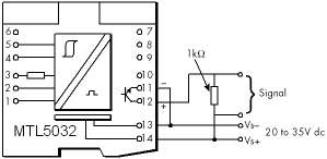
I cannot get an output from the SAFE side of a MTL5032. What is the problem?
The output terminals 11 and 12 are not powered so you will have to provide the voltage. Below is a typical circuit showing a 24 VDC supply.
-
I have a control cabinet and some transmitters I want to protect. If I protect the power and the signal lines at the control cabinet end will the transmitters be protected?
No, if surge current is present on the signal lines it will be seen on both ends of the lines. Properly protecting the power and signal lines at the control cabinet end will only protect the control cabinet. Surge protection must also be installed at the transmitters if they are to be protected.
-
I have product which I would like to use in a SIL loop; as MTL are a certified FSM company can they provide certification for my product?
No. We are only responsible for our own products.
-
If a "hacker" manages to obtain a copy of the CMP (Central Management Platform) software and connect it to my network, could he take over my Tofino?
ABSOLUTELY NOT - Each CMP database has a unique random key. The first time a CMP establishes a connection to new Tofino appliance, it uploads its random key to that Tofino. From then on that Tofino can only communicate with the CMP that owns the key.
-
If a Tofino appliance doesn’t have an IP address, how can I communicate to it over an IP network?
The Tofino uses a patent-pending technology to “borrow” IP addresses of the devices that it will be protecting for its configuration and event messages. This does not impact the devices being protected in any way, but it makes the Tofino almost impossible for hackers to detect.
-
Is a defense-in-depth strategy important for all control systems or is it just needed for very critical safety systems?
A defense-in-depth strategy is needed for all control systems. The North American Electrical Reliability Council (NERC) notes that poor defense in depth design is the second most common security vulnerability in modern control systems.
-
Is full protection going to be too expensive?
Full protection is one of the most inexpensive insurance policies you can buy. The cost of system inavailability is far more expensive than proper protection. One major surge event in a ten-year period far outweighs the cost of protection.
-
Is it true that if a safety loop is designed as SIL2 then all the individual components in that loop should be rate to be used in SIL2 as well?
This is the simplest way to achieve the goal but remember that duplication or triplication of the signal paths is often used to reach the target too. Thus components with lower ratings are employed in parallel to implement the overall safety function, which reduces the demands upon the individual items.
-
Is lightning my only concern when I am considering surge protection?
No, actually the majority of premature equipment failures from surge impulses are caused by much lesser events than direct lightning strikes. Small electrical impulses caused from other users on our same power grid, utility grid switching, electrical motors, and many other sources cause the majority of surge related failures in today’s electronic equipment. These smaller impulses will degrade the minute internal junctions inside IC chips over time and cause premature failure.
-
Is the change-over to redundant FISCO 'bumpless' ?
Yes. Interruption of fieldbus communications is momentary, and is accommodated by the re-transmission mechanism that is implicit in the Foundation fieldbus protocol. There will therefore be no loss of control, and the plant operator will observe no loss of data.
-
Most MTL surge protection devices for signal and communication devices indicate that they have a hybrid circuit. What is the advantage of the hybrid in the MTL devices?
This allows our surge protection devices to have a high surge current capacity (so they are not easily damaged from nearby lightning strikes) and precise limiting voltage characteristics (so the voltage seen at your equipment has been limited to a very low level).
-
MTL 55xx series of products are certified for use in hazardous areas so could they all be allowed to be used in safety systems?
No. With our isolator products Intrinsic Safety relates to the prevention of explosion by constraining the electrical energy passed into the hazardous area under all conditions, both in normal operation and including when faults are present. The risks that are mitigated by the safety functions are concerned with the process under control and maintaining this in a safe state.
-
MTL show the Safety Description of the zener barriers on the data sheet, but it only shows voltage, resistance and current. A number of field equipment certificates also show power. Do I have to confirm that the barrier has a value for power that is acceptable and how can I check this?
Yes, you have to ensure that the barrier power value is not greater than the power value given for the field equipment.
The maximum power transfer between the safe area and the field takes place when the impedance of the source is equal to the impedance of the load. This is called the Matched Power.
This is the worst case condition and so this is used to calculate the power output from a barrier. Under these conditions the power can be expressed as:-
Matched Power = Voc x Isc / 4 (W)
For a typical 24V dc barrier, MTL7728+, with safety description 28v, 93mA.
28 x 0.093 = 2.604
2.604 / 4 = 0.651W
However the power value for each channel of a barrier is provided in the Maximum Cable Parameters table for each barrier series. -
MTL4041B - What is the input resistance at hazardous area pins 5 and 6?
Less than 50 ohms, and typically 30 ohms.
-
MTL4073 - What is the hazardous input resistance and safe area output impedance ?
10V/m with 1kHz sine wave modulation to 80% of the carrier level are the minimum RF levels specified in the Generic Immunity Standard for Industrial Environments EN50082 part 2.
-
MTL5000 Series - What crimp ferrules are available for 1.5mm2 wire ?
We have not been able to locate any ferrules with 12mm length metal tubes for 1.5mm2 wire in any supplier catalogues (unless you have seen any?!).
We recommend you use the following 18mm metal tube length ferrules:-
PKE1518 (1.5mm2) and PKE2518 (2.5mm2) from Cembre, and cut them to 12mm length after crimping. -
MTL5042; what is the safety description for terminals 1 and 3?
Non-energy storing apparatus can be connected between terminals 1 and 3.
See under ‘Safety description, Terminals 1 to 3’ in the MTL5042 data specification.
Terminals 1 and 3 can be connected into an IS loop as long as the open circuit voltage <28 V. Therefore, determine the output safety parameters for the field device and ensure they comply with this voltage.There are no specific cable parameter figures provided for this combination of terminals on that certificate. The only reference to cable parameters on the certificate is on page 3:-
“The capacitance and either the inductance or the inductance to resistance ratio (L/R) of the load connected to the output terminals must not exceed the following values: Group IIC - Co < 0.13uF, Io < 4.2mH or L/R < 55uH/ohm" -
MTL55xx isolator datasheet stats that it could be used in SIL3 rated safety function loops so can this be used in SIL2 rated safety function loops?
Look at the definitions of the safety integrity levels. If a component has been assessed as suitable for use up to SIL3 then it can also be used in loops that need to achieve SIL2 or SIL1.
-
My control system is never connected to the Internet. Am I still at risk from cyber incidents?
Absolutely - most attacks enter the system from either the business network or through secondary pathways such as infected laptops, USB keys, remote access over Virtual Private Networks (VPNs) or modems.
-
My control system is separated from the business network with a firewall. Do I still need additional security?
Many attacks come through secondary pathways such as infected laptops, remote access over VPNs, and modems that will completely bypass the firewall. To address this, the critical devices inside the control system firewall should be given additional layers of protection (eg: office PCs have personal firewalls and anti-virus software). This is known as a defense-in-depth strategy
-
My DCS vendor says that their protocol has authentication or has been security-certified. Do I still need a Tofino?
If the DCS only uses that authenticated protocol and that protocol has been security tested by a certification service such as MUSIC or Idaho National Labs, then the protocol is probably secure. However, many products also communicate using older un-authenticated protocols such as Ethernet/IP, MODBUS, HTTP or telnet.
-
My transmitter only cost $1,000.00 so why should I consider spending $200.00 to protect it from surge events?
There are many things to consider when you are justifying the cost to protect. More important than the actual replacement cost of the transmitter is the loss of the function of the transmitter. Usually the functional loss associated with the loss of the transmitter for a period of time is the main justification in providing protection. Another justification to consider is the labor cost and travel cost that could be incurred in the repair.
-
On the MTL AC mains panels surge protection cut sheets they indicate the product is for a 120/240V single phase (split phase) system, i.e. ZD16100 or ZM11200. Does this mean that the product will work with either a 120V or a 240V single phase mains service?
No, a 120/240V single phase (split phase) is a unique electrical service mainly seen only in the Americas and Japan. The 120/240V single phase (split phase) products have two separate 120V legs a neutral and a ground. Products designed for this service will not work on 230V or 240V single phase systems. Products designed for 120/240V single phase (split phase) applications would be immediately damaged when connected to 230V or 240V single phase services.
-
Our equipment is connected to a UPS, do we still need surge protection?
UPS systems play a very important part in an overall power protection plan. They are designed to provide good clean uninterruptible power to critical equipment. They provide no protection for the communication and control lines found in today’s network type environments. They also do not normally provide AC power protection to the many nodes connected within the network. The surge protection elements found within even a very large UPS is very small in comparison to stand-alone SPD’s. Normally around 25 to 40kA. In comparison, our smallest AC entrance protector is 70kA and our largest is 600kA.
-
Should CMP (Central Management Platform) be always online? What happens if CMP is down? Will network security be breached?
If the CMP is shut down there is no risk to security whatsoever. We suggest that the Tofino CMP is left online at all times so it can collect events from Tofinos in the field and provide alarms to the operator, however this is strictly optional.
-
Should I install a separate ground for the surge protection device?
No, the surge suppressor should be grounded to the same ground reference as the equipment it is protecting.
-
We are based in an area with very little lightning, why do we need surge protection?
Many areas of the world do not experience as much lightning related problems as others. As much as companies today depend on their control and network systems, the system availability has become paramount. For most companies, a single surge related incident in a ten-year period, which causes the loss of system availability, would more than pay for proper protection.
-
We have good grounding, do we still need surge protection?
A good ground is important for surge protection devices (SPD) to work properly. AC power SPD’s are designed to divert surge current to ground by providing the least resistive path. Without surge protection on the AC power, the surge current will look for other paths to a good ground. In many cases this path is found through electric/electronic equipment. Once the dielectric strength of the components in electronic equipment has been surpassed large currents begin to flow through the sensitive electronics thus causing failure.
-
We’ve never had any problems with surges, why do we need surge protection?
There are not many areas of the world today that do not experience surge-related incidents. Lightning is only one of the many causes of transient surge related problems. Today’s modern electronic equipment is much smaller, much faster, and much more susceptible to transient related problems than was the last generation of equipment. The sheer number of control and communication devices interlinked together in today’s networks make their susceptibility many times greater. These are new problems that were not nearly as frequent with previous generations of control equipment.
-
What allowance do I make for field device inrush current when designing a FISCO/FNICO segment?
When designing a segment with a FISCO or FNICO power supply no allowance needs to be made for inrush current. The IEC61158-2 fieldbus standard allows fieldbus devices to draw up to 20mA above their design current for up to 20ms on start up.
The current limit of the FISCO and FNICO power supplies is at least 20mA above the design current used for segment calculations. This means that if a device is disconnected from a fully loaded segment; on reconnection, it can briefly draw up to 20mA above the design current, without affecting the normal operation of the segment.
The FISCO and FNICO power supplies have a soft start feature to ensure the fieldbus segment starts up. For example for a segment with 16 x 15mA devices powered by a 9122-IS IIB FISCO power supply, the segment will normally require 240mA which is less than 265mA 9122-IS design current. On start up the segment could have an initial current draw requirement of 240mA + 16 x 20mA in rush current or 560mA. The 9122-IS will supply at least 285mA for up to 1 sec, which is long enough to power up all the field devices. In the MTL fieldbus test laboratory we have proven that the segment will start up when fully loaded with devices with the highest in rush currents, confirming that with MTL power supplies no additional allowance should be made for in rush current in segment calculatlions. -
What allowance do I need to make for the fieldbus signal when designing a segment?
No allowance needs to be made for the fieldbus signal if the segment uses a FISCO or FNICO power supply. As the fieldbus signal is symmetrical, the terminators act as a current source/sink for the fieldbus signal, so no extra current is drawn from the power supply.
-
What allowance do I need to make if using a SpurGuarded™ Megablock with a FISCO power supply?
The F240-F259 range of Relcom SpurGuard™ed Megablocks are designed for IS applications and are ideal for providing wiring connections on a FISCO segment. The F251 8-way Megablock normally draws 3.5mA plus the current for any devices connected. In the event ot a device having a short circuit, that device will now draw a maximum of 42mA instead of its normal current (e.g. 15mA).
For example, consider a segment with sixteen 15mA devices connected via two F251 8 way Megablocks powered by a 9122-IS IIB FISCO power supply. The segment will normally require (16 x 15 + 2 x 3.5 =) 247mA which is less than the 265mA 9122-IS design current.
If a single spur has a short cicuit, the current consumption will be 247 + 42 –15mA = 274mA, which is still less than the 285mA current limit of the 9122-IS, so this segment design is OK.
Additionally, you will need to check that the voltage at the devices will always be greater than 9V. Some designers use a minimum of 10V at a device to provide some margin.
An MTL-Relcom segment calculator is available which will automatically complete all these calculations for you. With typical type A cable (0.8 sq.mm, 44 ohm/loop km) and all devices at the end of the trunk connected by 30m spurs the maximum permitted trunk length would be 330m. Under the same conditions but with 1.5 sq.mm, 22 ohm/loop km cable, the maximum permitted trunk length would be 660m.
On the few occasions when longer trunks are required, either fewer field devices could be connected to the segment or, alternatively, the FISCO power supply could be mounted in a Zone 2 hazardous area, close to the field devices. -
What are the maximum interconnection cable lengths?
The maximum recommended length of 20 way HART ribbon cable between the BPHM64 backplane and the HART connection unit or IS backplane is 6 metres or 20 feet. Flat ribbon cables should not be taken outside the cabinet as they are not robust and susceptible to noise. Ground loops may also be an issue. If possible, locate the HART mux units close to the take-off points. For larger distances use more than one BPHM64 with MTL4841 modules fitted and link via the RS485 bus.
The maximum length of 10 way interface bus cable between a single MTL4841 communications module and up to 16 MTL4842 HART interface modules / backplanes is 4 metres or 13 feet, (between modules 1 and 16).